
Page 12 - Parker - Equipment
P. 12
4300 Catalog Equipment
Benders
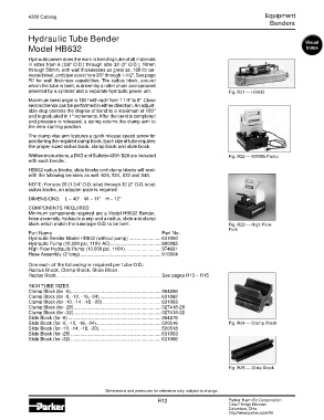
Hydraulic Tube Bender
Model HB632
Hydraulic power does the work in bending tube of all materials
in sizes from 6 (3/8” O.D.) through size 32 (2” O.D.), 10mm
through 50mm, with wall thicknesses as great as .188 for an-
nealed steel, and pipe sizes from 3/8” through 1-1/2”. See page
R7 for wall thickness capabilities. The radius block, around
which the tube is bent, is driven by a roller chain and sprocket
powered by a cylinder and a separate hydraulic power unit. Fig. R21 — HB632
Maximum bend angle is 180° with radii from 1 1/4” to 8”. Close
second bends can be performed in either direction. An adjust-
able stop controls the degree of bend to a maximum of 180°
and is graduated in 1° increments. After the bend is completed
and pressure is released, a spring returns the clamp arm to
the zero starting position.
The clamp vise arm features a quick release speed screw for
positioning the required clamp block. Each size of tube requires
the proper sized radius block, clamp block and slide block.
Written instructions, a DVD and Bulletin 4391-B26 are included Fig. R22 — 900085 Pump
with each bender.
HB632 radius blocks, slide blocks and clamp blocks will work
with the following benders as well: 624, 824, 832 and 848.
NOTE: For size 28 (1 3/4” O.D. tube) through 32 (2” O.D. tube)
radius blocks, an adapter plate is required.
DIMENSIONS: L – 40” W – 11” H – 12”
COMPONENTS REQUIRED
Minimum components required are a Model HB632 Bender,
hose assembly, hydraulic pump and a radius, slide and clamp
block which match the tube/pipe O.D. to be bent. Fig. R23 — High Flow
Pum
Part Name Part No.
Hydraulic Bender Model HB632 (without pump) ........................ 631050
Hydraulic Pump (10,000 psi, 110V AC) ...................................... 900085
High Flow Hydraulic Pump (10,000 psi, 110V) ........................... 974691
Hose Assembly (3’ long) ............................................................. 910004
One each of the following is required per tube O.D.:
Radius Block, Clamp Block, Slide Block.
Radius Block ............................................................................... See pages R13 – R15
INCH TUBE SIZES
Clamp Block (for -6) .................................................................... 864266
Clamp Block (for -8, -12, -16, -24) .............................................. 631092
Clamp Block (for -10, -14, -18, -20) ............................................ 631093
Clamp Block (for -28) .................................................................. 027418-28
Clamp Block (for -32) .................................................................. 027418-32
Slide Block (for -6) ...................................................................... 864276
Slide Block (for -8, -12, -16, -24) ................................................. 520516 Fig. R24 — Clamp Block
Slide Block (for -10, -14, -18, -20) ............................................... 520518
Slide Block (for -28) .................................................................... 631063
Slide Block (for -32) .................................................................... 631066
Fig. R25 — Slide Block
Dimensions and pressures for reference only, subject to change.
R12 Parker Hannifin Corporation
Tube Fittings Division
Columbus, Ohio
http://www.parker.com/tfd