
Page 14 - Parker - Coils and Electronics
P. 14
Catalog HY15-3502/US DS Coil
Technical Information Series 5/8″″ ″″ ″ I.D.
CV
Features
• Compact one piece encapsulated design
• Minimal amperage draw
Valves
Check
SH
• Numerous terminals and voltages
• High watt design optional
• Heavy gauge color coded lead wire with built-in strain
Valves
Shuttle
relief
LM
• 180°C Class H wire standard
• 200°C Class N wire on high watt models
Load/Motor
Controls
FC
Specifications
Wattage 17 Watts — Standard - Black Coil
Flow
Controls
30 Watts — High Watt - Red Coil
PC
Duty Rating Continuous @ 100% voltage
Wire Class Class H for all voltages 17 Watt
Pressure
Controls
Class N for all voltages 30 Watt
LE Symbol
A.C. Rectifier Integral full wave bridge
Lead Wire 18 gauge 24″ long, 600 volt rating
Elements
Logic
DC
Lead Wire 34 kg (75 lbs.) @ 21°C (70°F) &
Strain Relief 18 kg (40 lbs.) @ 93°C (200°F)
Encapsulating Glass filled nylon, resistant to
Controls
Directional
Material moisture, caustic solutions, fungus,
MV
and temperatures from
-40°C (-40°F) to 200°C (392°F)
Manual
Valves
SV
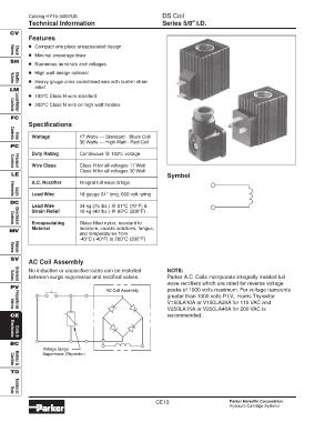
AC Coil Assembly
No inductive or capacitive loads can be installed NOTE:
between surge suppressor and rectified valves. Parker A.C. Coils incorporate integrally molded full
Valves
Solenoid
wave rectifiers which are rated for reverse voltage
PV
AC Coil Assembly peaks of 1000 volts maximum. For voltage transients
greater than 1000 volts P.I.V., Harris Thyrector
V150LA10A or V150LA20A for 115 VAC and
V250LA15A or V250LA40A for 200 VAC is
Proportional
Valves
CE recommended.
Electronics
Coils &
BC
Voltage Surge
Suppressor (Thyrector)
Bodies &
Cavities
TD
Data
Technical
CE13 Parker Hannifin Corporation
Hydraulic Cartridge Systems