
Page 3 - Parker - Coils and Electronics
P. 3
Catalog HY15-3502/US
Technical Tips Coils and Electronics
CV
COMMON OPTIONS
Below are some of the common options to the Unicoil product offering.
Continuous Duty: Parker’s standard line of coils are Voltages: Parker has a wide selection of coils avail- Check Valves
rated for continuous duty operation. This means the able to meet your needs. Most coil terminations are SH
coil can be left on continuously without fear of the available with our standard voltages of 12V and 24V in
magnet wire insulation breakdown, when used in DC, and 120V and 240V in AC. Voltages 6V, 10V, 18V,
standard climate conditions. The Unicoils and Super 36V, 48V DC and 440V AC are also available for many Shuttle Valves
Coils are made of a high quality Class N magnet wire. termination types at a slight premium. Contact your
This Class N rating signifies the internal wires are Parker representative should your application call for LM
rated to 200°C (392°F). voltages other than our standard offering.
Continuous duty does not mean the coil will have the Diodes: The Parker Coils can be ordered with a diode Load/Motor Controls
same amount of power after hours of operation as it molded internally. Parker Unicoils use a IN5062 diode.
had at initial actuation. Coils do heat up during use. The Super Coils use a IN5627 diode. Diodes are FC
This internal heat rise increases the resistance of the sometimes used to protect sensitive, downstream
coil and thus, decreases the current (V = IR). The electrical components from potential surges from the
performance curves presented on the solenoid valve coil. By internally molding the diode into the coil, you Flow Controls
pages are based on a coil at room temperature and can reduce the assembly time
85% of voltage. Thus, when using a valve in continu- and cost associated with PC
ous duty applications, you may need to derate the externally wiring a diode.
performance. In short, the continuous duty rating One should be careful Pressure Controls
signifies that while the coil will get hot during use and not to switch the polarity
resistance will increase, it will not generate enough (“+” and “-” terminals), when wiring a coil with an
heat to damage the coil. internal diode. If these terminals are switched, the first LE
time voltage is applied to the coil; the short circuit will
Terminations: Parker offers a wide variety of coil destroy the diode and render the coil use-less. Parker Elements
terminations for all coils to meet the demands of your coils with diodes have “+” and “-” molded near the Logic
application. Over the years, the dual lead wire and dual termination outlet to help identify polarity. DC
spade offerings have been popular due to their ease of
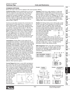
installation and availability. In the past few years, the DIN Connectors: Parker does offer connectors for use
demand for more secure termination connections has with the DIN style coils. As shown below, the DIN Directional Controls
increased. In addition, the integral connectors reduce connectors are available in both rectified and non-
cost and improve integrity by reducing the number of rectified forms. The cable gland versions can be MV
connections. As such, the Amp Junior, Weatherpack, ordered for type PG9 or PG11.
Metri-Pack, and Deutsch have increased in popularity. 1.57 .39
We offer these connectors on a lead wire coil, as well Cable Gland Manual Valves
as an internally molded version of the DIN, Amp Type Non-Rectified Rectified
Junior, and Metri-Pack coils. If you do not find your PG9 710549-00 712126-01 1.04 SV
desired coil termination in our catalog, contact your PG11 710549-01 712126-00
factory sales representative. We have added a Sealed
Leadwire option to meet IP69K requirements yet still .06 Solenoid Valves
allow for other lead wire options. 1.04
PV
Current Types: Both direct current (DC) and alternat- 1.04
ing current (AC) versions are available for the Parker Proportional
line of coils. The AC versions are essentially DC coils Valves
with a full wave rectifier integrally molded into the coil. Conduit Rectified Conduit Non-Rectified
The rectifiers are rated for voltage peaks up to 1000 712704-00 710549-02 CE
volts maximum. For voltage transients greater than
1000 volts, a Harris Thyrector is recommended. The 2.45 1.57 Coils & Electronics
AC coils operate at 50/60 cycles (Hz). Since the AC
versions are rectified
AC Coil Assembly 1.37 1.04 BC
DC coils, there is
.06
no inrush current
like with “true” .06 .22 Bodies & Cavities
AC coils. It .22 1.04
1.06
also means TD
DC coils and
AC coils are 1.06 Ø 1.00 1.04
Voltage Surge Technical
interchangeable. Suppressor (Thyrector) Data
CE2 Parker Hannifin Corporation
Hydraulic Cartridge Systems