
Page 95 - Wieland - Selos/Fasis
P. 95
fasis
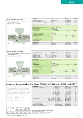
WKFN 4 TKG with SiST Description Type Part No. Std. Pack
Disconnect block, gray WKFN 4 TKG/35 56.704.4055.0 100
• Disconnect block with tension spring connection
for mounting on TS 35 Fuse holder for fuse 5 x 20 Si ST Z1.299.4055.0 10
Fuse holder with indicator (24 V) 2) Si ST LED Z1.299.4155.0 10
• Nominal cross section 4 mm 2 Fuse holder with indicator (220 V) 2) Si ST GL Z1.299.4255.0 10
General data
Width / length / height, incl. TS 7.5 6 mm / 82 mm / 38 mm
Wire strip length 11 mm
Approvals EMD'
Technical data IEC UL CSA
EN 60 947-7-3
Cross section fine-stranded 0.13 – 4 mm 2
Cross section solid/stranded 0.13 – 6 mm 2
Cross section, AWG 24 – 10 22 – 10
Rated current 1) 1) 10 A 1)
Rated voltage 500 V 2) 600 V 2) 300 V 2)
Rated impulse voltage 8 kV
Pollution degree 3
Accessories Type Part No. Std. Pack
End plate, gray APFN 4 D2/2 07.312.9055.0 10
Partition, gray TWFN 4 D2/2 07.312.9155.0 10
WKFN 4 TKG with DiST Description Type Part No. Std. Pack
Disconnect block, gray WKFN 4 TKG/35 56.704.4055.0 100
• Disconnect block with tension spring connection 1)
for mounting on TS 35 Diode plug – empty J max = 10 A DIST ... Z1.299.3055.0 10
Diode plug – diode J max = 1 A 1) DIST-1 N 4007-1 3) Z1.299.3155.0 10
• Nominal cross section 4 mm 2 Diode plug – diode J max = 1 A 1) DIST-1 N 4007-2 4) Z1.299.3355.0 10
Diode plug with jumper J max = 10 A 1) DIST-D Z1.299.3255.0 10
General data
Width / length / height, incl. TS 7.5 6 mm / 82 mm / 38 mm
Wire strip length 11 mm
Approvals EMD
Technical data IEC UL CSA
EN 60 947-7-3
Cross section fine-stranded 0.13 – 4 mm 2
Cross section solid/stranded 0.13 – 6 mm 2
Cross section, AWG 24 – 10 22 – 10
Rated current 1) 1) 10 A 1)
Rated voltage 500 V 2) 600 V 2) 300 V 2)
Rated impulse voltage 8 kV
Pollution degree 3
Accessories Type Part No. Std. Pack
End plate, gray APFN 4 D2/2 07.312.9055.0 10
Partition, gray TWFN 4 D2/2 07.312.9155.0 10
Info and Accessories for fasis WKFN 4 TKG with SiST and DiST
Accessories Type Part No. Std. Pack
1) The current is determined by the inserted fuse.
Cross connector, insulated 2 pole IVB WKF 4-2 Z7.261.1227.0 10
2) The voltage range is determined by the built-in LED display.
Depending on the application and the installation method, the 3 pole IVB WKF 4-3 Z7.261.1327.0 10
circumstances for increased temperature must be checked in the 4 pole IVB WKF 4-4 Z7.261.1427.0 10
closed fuse holders. 5 pole IVB WKF 4-5 Z7.261.1527.0 10
Higher ambient temperatures are an additional load for the fuse 6 pole IVB WKF 4-6 Z7.261.1627.0 10
inserts. Therefore, the reduction of the rated current must be
considered accordingly in these applications. 7 pole IVB WKF 4-7 Z7.261.1727.0 20
Indicator (24 V): LED, red 8 pole IVB WKF 4-8 Z7.261.1827.0 20
current consumption: 10.3 mA 9 pole IVB WKF 4-9 Z7.261.1927.0 20
Indicator (220 V): LED, red 10 pole IVB WKF 4-10 Z7.261.2027.0 20
current consumption: 0.3 mA Wire entry guide 0.13 – 0.2 mm 2 LEL 4/1 WEISS 05.561.8553.0 100
3) / 4) Periodic peak voltage 1000 V 2
Direction Anode Cathode 3) 0.25 – 0.5 mm LEL 4/2 GRAU 05.561.8653.0 100
of the diode: Cathode Anode 4) 0.75 – 1.0 mm 2 LEL 4/3 SCHWARZ 05.561.8753.0 100
Cover with warning symbol over 4 blocks yellow ADF 4/4 GELB 04.343.6153.8 10
Test adapter, modular ST 2/2,3 Z5.553.2921.0 10
Screwdriver, uninsulated DIN 5264 B 0,6x3,5 06.502.4000.0 5
Screwdriver, uninsulated, MINI DIN 5264 B 0,6x3,5 M 06.502.5000.0 10
Rated Exclusive short-
Type Overload protection
voltage circuit protection
Single Group Single Group
arrangement arrangement arrangement arrangement When selecting G fuse inserts, make sure that the specified
maximum power is not exceeded.
SIST 250 V 1.6 W 1.6 W 2.5 W 1.6 W Maximum power loss at 23° C ambient temperature
(according to DIN EN 60947-7-3)
Technical information see facts & data page 146 ff. 95