Page 503 - Mechatronics with Experiments
P. 503
October 9, 2014 8:41 254mm×178mm
                                         Printer: Yet to Come
                        JWST499-Cetinkunt
            JWST499-c07
                                                            ELECTROHYDRAULIC MOTION CONTROL SYSTEMS  489
                             In order to make the current–main spool displacement a proportional relationship, like the
                             case in a single stage valve, there has to be a “feedback mechanism” on the main spool
                             position. The pilot spool position is determined by the solenoid force and the feedback from
                             the main spool position. The feedback from the main spool to pilot spool may be in the
                             form of a mechanical linkage, spring, pressure, or in the form of an electronic sensor signal
                             to a controller. Let us consider a two stage valve which uses pressure feedback between
                             the pilot and main stage (Figure 7.64). The pressure feedback from the main spool position
                             acts like a balancing spring against the solenoid force
                                                           1
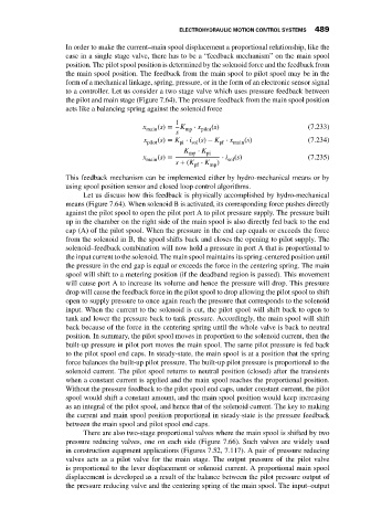
                                                  x   (s) =  K  ⋅ x  (s)                       (7.233)
                                                   main       mp  pilot
                                                           s
                                                   x  (s) = K ⋅ i (s) − K ⋅ x  (s)             (7.234)
                                                    pilot   pi  sol    pf  main
                                                              K mp  ⋅ K pi
                                                  x main (s) =          ⋅ i (s)                (7.235)
                                                                         sol
                                                           s + (K ⋅ K mp )
                                                                pf
                             This feedback mechanism can be implemented either by hydro-mechanical means or by
                             using spool position sensor and closed loop control algorithms.
                                  Let us discuss how this feedback is physically accomplished by hydro-mechanical
                             means (Figure 7.64). When solenoid B is activated, its corresponding force pushes directly
                             against the pilot spool to open the pilot port A to pilot pressure supply. The pressure built
                             up in the chamber on the right side of the main spool is also directly fed back to the end
                             cap (A) of the pilot spool. When the pressure in the end cap equals or exceeds the force
                             from the solenoid in B, the spool shifts back and closes the opening to pilot supply. The
                             solenoid–feedback combination will now hold a pressure in port A that is proportional to
                             the input current to the solenoid. The main spool maintains its spring-centered position until
                             the pressure in the end gap is equal or exceeds the force in the centering spring. The main
                             spool will shift to a metering position (if the deadband region is passed). This movement
                             will cause port A to increase its volume and hence the pressure will drop. This pressure
                             drop will cause the feedback force in the pilot spool to drop allowing the pilot spool to shift
                             open to supply pressure to once again reach the pressure that corresponds to the solenoid
                             input. When the current to the solenoid is cut, the pilot spool will shift back to open to
                             tank and lower the pressure back to tank pressure. Accordingly, the main spool will shift
                             back because of the force in the centering spring until the whole valve is back to neutral
                             position. In summary, the pilot spool moves in proportion to the solenoid current, then the
                             built-up pressure in pilot port moves the main spool. The same pilot pressure is fed back
                             to the pilot spool end caps. In steady-state, the main spool is at a position that the spring
                             force balances the built-up pilot pressure. The built-up pilot pressure is proportional to the
                             solenoid current. The pilot spool returns to neutral position (closed) after the transients
                             when a constant current is applied and the main spool reaches the proportional position.
                             Without the pressure feedback to the pilot spool end caps, under constant current, the pilot
                             spool would shift a constant amount, and the main spool position would keep increasing
                             as an integral of the pilot spool, and hence that of the solenoid current. The key to making
                             the current and main spool position proportional in steady-state is the pressure feedback
                             between the main spool and pilot spool end caps.
                                  There are also two-stage proportional valves where the main spool is shifted by two
                             pressure reducing valves, one on each side (Figure 7.66). Such valves are widely used
                             in construction equpment applications (Figures 7.52, 7.117). A pair of pressure reducing
                             valves acts as a pilot valve for the main stage. The output pressure of the pilot valve
                             is proportional to the lever displacement or solenoid current. A proportional main spool
                             displacement is developed as a result of the balance between the pilot pressure output of
                             the pressure reducing valve and the centering spring of the main spool. The input–output

