Page 804 - Mechatronics with Experiments
P. 804
790   MECHATRONICS
                                4. Experiment with different PWM duty cycles and PWM frequencies. Try to feel the
                                   net force generated as a function of PWM duty cycle while holding the solenoid at a
                                   fixed mid position.
                                5. (Optional) Obtain a proportional single stage valve with two proportional solenoids,
                                   spool position sensor, and centering spring. Connect two PWM output pins from
                                   the PIC microcontroller to drive two transistors to control two solenoids. Under
                                   software control, control either one of the solenoids proportionally under software
                                   control. Verify the spool position change as function of the solenoid (number 1 or
                                   number 2) and the magnitude of the command signal sent to the solenoids by the PIC
                                   microcontroller.


                       11.10 EXPERIMENT 10: STEPPER MOTOR MOTION
                                CONTROL USING A PIC MICROCONTROLLER

                              Objective
                              Design a complete system for motion control of a stepper motor using the PIC microcon-
                              troller and a step motor controller integrated circuit (IC). Write software to control
                                1. magnitude of speed,
                                2. direction of speed,
                                3. run the motor in full-step mode and half-step mode.


                              Components

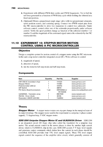
                              Item                      Quantity   Part No.       Supplier
                              EDE1200 IC (translator chip)  1      141532         www.jameco.com
                              Stepper Motor                1       151861         www.jameco.com
                              Potentiometer (200 Ω)        1       181972         www.jameco.com
                              DIP Switch                   1       38818          www.jameco.com
                              PIC Demo Board/connectors  1 set     DM163022 or    www.microchipdirect.com
                                                                     DV164006
                              ULN2003A - Transistor array  1       60K7049        www.newark.com
                              IN4744 - Zener diode         1       36185          www.jameco.com
                              Resonator: AWCR 4.00 MD      1       13J2002        www.newark.com


                              Theory

                              Stepper Motor    A stepper motor rotates one step per change in the energized state of
                              its stator windings. The stepper motor used in the experiment is a unipolar, 2-phase (center
                              tapped), 7.5 degrees/step, 5 VDC stepper motor.

                              EDE1200 Unipolar Stepper Motor IC and ULN2003A Driver           EDE1200
                              is an integrated circuit (IC) logic chip (also called the translator) for a unipolar step
                              motor. The actual current control in the motor phases is done by another high current
                              driver, which is ULN2003A chip in this case. EDE1200 accepts 5 V logic level signals
                              and generates output commands which define how the current in each phase should be
                              controlled. EDE1200 provides four TTL level output signals. These TTL-level output
                              signals control the sequence of the amplifier drive circuit, which generally consists of

