
Page 802 - Mechatronics with Experiments
P. 802
788 MECHATRONICS
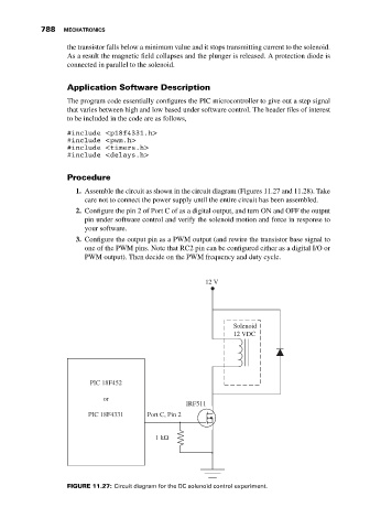
the transistor falls below a minimum value and it stops transmitting current to the solenoid.
As a result the magnetic field collapses and the plunger is released. A protection diode is
connected in parallel to the solenoid.
Application Software Description
The program code essentially configures the PIC microcontroller to give out a step signal
that varies between high and low based under software control. The header files of interest
to be included in the code are as follows,
#include <p18f4331.h>
#include <pwm.h>
#include <timers.h>
#include <delays.h>
Procedure
1. Assemble the circuit as shown in the circuit diagram (Figures 11.27 and 11.28). Take
care not to connect the power supply until the entire circuit has been assembled.
2. Configure the pin 2 of Port C of as a digital output, and turn ON and OFF the output
pin under software control and verify the solenoid motion and force in response to
your software.
3. Configure the output pin as a PWM output (and rewire the transistor base signal to
one of the PWM pins. Note that RC2 pin can be configured either as a digital I/O or
PWM output). Then decide on the PWM frequency and duty cycle.
12 V
Solenoid
12 VDC
PIC 18F452
or
IRF511
PIC 18F4331 Port C, Pin 2
1 kΩ
FIGURE 11.27: Circuit diagram for the DC solenoid control experiment.