Page 797 - Mechatronics with Experiments
P. 797
LABORATORY EXPERIMENTS  783
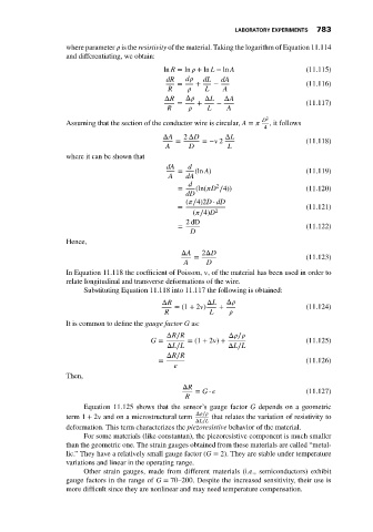
                             where parameter    is the resistivity of the material. Taking the logarithm of Equation 11.114
                             and differentiating, we obtain:

                                                        ln R =ln    +ln L −ln A               (11.115)
                                                        dR    d    dL  dA
                                                           =    +    −                        (11.116)
                                                         R         L    A
                                                        ΔR    Δ    ΔL   ΔA
                                                           =     +    −                       (11.117)
                                                         R          L    A
                             Assuming that the section of the conductor wire is circular, A =     D 2  , it follows
                                                                                   4
                                                        ΔA   2 ΔD       ΔL
                                                           =      =−   2                      (11.118)
                                                        A      D         L
                             where it can be shown that
                                                         dA   d
                                                            =   (ln A)                        (11.119)
                                                         A    dA
                                                              d       2
                                                            =   (ln(  D ∕4))                  (11.120)
                                                              dD
                                                              (  ∕4)2D ⋅ dD
                                                            =                                 (11.121)
                                                                (  ∕4)D 2
                                                              2dD
                                                            =                                 (11.122)
                                                               D
                             Hence,
                                                             ΔA   2ΔD
                                                                =                             (11.123)
                                                             A     D
                             In Equation 11.118 the coefficient of Poisson,   , of the material has been used in order to
                             relate longitudinal and transverse deformations of the wire.
                                  Substituting Equation 11.118 into 11.117 the following is obtained:
                                                       ΔR          ΔL    Δ
                                                           = (1 + 2  )  +                     (11.124)
                                                        R           L
                             It is common to define the gauge factor G as:
                                                         ΔR∕R            Δ  ∕
                                                    G =       = (1 + 2  ) +                   (11.125)
                                                         ΔL∕L            ΔL∕L
                                                         ΔR∕R
                                                      =                                       (11.126)

                             Then,
                                                             ΔR
                                                                = G ⋅                         (11.127)
                                                              R
                                  Equation 11.125 shows that the sensor’s gauge factor G depends on a geometric
                                                                Δ  ∕
                             term 1 + 2   and on a microstructural term  that relates the variation of resistivity to
                                                                ΔL∕L
                             deformation. This term characterizes the piezoresistive behavior of the material.
                                  For some materials (like constantan), the piezoresistive component is much smaller
                             than the geometric one. The strain gauges obtained from these materials are called “metal-
                             lic.” They have a relatively small gauge factor (G = 2). They are stable under temperature
                             variations and linear in the operating range.
                                  Other strain gauges, made from different materials (i.e., semiconductors) exhibit
                             gauge factors in the range of G = 70–200. Despite the increased sensitivity, their use is
                             more difficult since they are nonlinear and may need temperature compensation.

