
Page 795 - Mechatronics with Experiments
P. 795
LABORATORY EXPERIMENTS 781
Components
Item Quantity Part No. Supplier
Aluminum beam (2 mm x 15 mm x 1000 mm) 1 1663T12 McMaster
(Cut into shorter lengths)
Strain gauge G = 2, R = 120 Ω 1 SG-6/120LY11 www.omega.com
(and bonding adhesive) 1 SG401 www.omega.com
LM358 Op-Amp IC 2 120862 (www.jameco.com)
Potentiometer (200 kΩ max) 1 241349 (www.jameco.com)
Resistor 120 Ω 2 30082 (www.jameco.com)
Resistor 100 kΩ 1 107764 (www.jameco.com)
Resistor 1000 Ω 1 30081 (www.jameco.com)
Breadboard 1 20722 (www.jameco.com)
Set of connection wires 1 set 20079 (www.jameco.com)
PIC Demo Board/connectors 1 DM163022 (www.microchip.com)
Theory
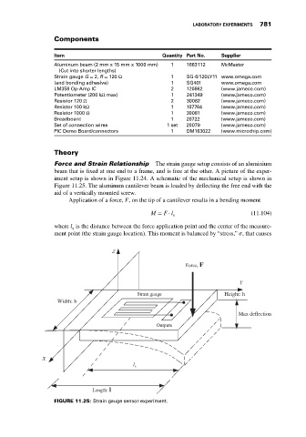
Force and Strain Relationship The strain gauge setup consists of an aluminium
beam that is fixed at one end to a frame, and is free at the other. A picture of the exper-
iment setup is shown in Figure 11.24. A schematic of the mechanical setup is shown in
Figure 11.25. The aluminum cantilever beam is loaded by deflecting the free end with the
aid of a vertically mounted screw.
Application of a force, F, on the tip of a cantilever results in a bending moment
M = F ⋅ l (11.104)
s
where l is the distance between the force application point and the center of the measure-
s
ment point (the strain gauge location). This moment is balanced by “stress,” , that causes
Height: h
Width: b
Max deflection
l s
FIGURE 11.25: Strain gauge sensor experiment.