
Page 790 - Mechatronics with Experiments
P. 790
776 MECHATRONICS
3. Learn the basic hardware and software features of PIC 18F452 or PIC 18F4431, and
software control a digital I/O channel.
4. To read the status of digital inputs: status of the DIP switches under software control.
5. To drive LEDs under software control by using digital output pins of an I/O port of
the PIC18F452 (or PIC 18F4431) microcontroller, and to change the status of LEDs
under software control based on digital inputs to the PIC microcontroller.
Microcontroller discussion is based on PIC 18F452. However, PIC 18F4331 has a
peripherial interface for quadrature encoder, and hence makes Experiment number 12 much
easier to handle. There are minor differences between the two models of this microcontroller
family. The reader should make the necessary adjustments depending on which model is
being used.
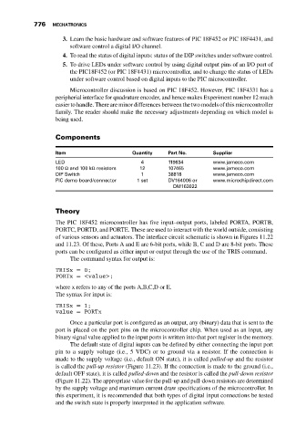
Components
Item Quantity Part No. Supplier
LED 4 119634 www.jameco.com
100 Ω and 100 kΩ resistors 12 107465 www.jameco.com
DIP Switch 1 38818 www.jameco.com
PIC demo board/connector 1 set DV164006 or www.microchipdirect.com
DM163022
Theory
The PIC 18F452 microcontroller has five input–output ports, labeled PORTA, PORTB,
PORTC, PORTD, and PORTE. These are used to interact with the world outside, consisting
of various sensors and actuators. The interface circuit schematic is shown in Figures 11.22
and 11.23. Of these, Ports A and E are 6-bit ports, while B, C and D are 8-bit ports. These
ports can be configured as either input or output through the use of the TRIS command.
The command syntax for output is:
TRISx = 0;
PORTx = <value>;
where x refers to any of the ports A,B,C,D or E.
The syntax for input is:
TRISx = 1;
value = PORTx
Once a particular port is configured as an output, any (binary) data that is sent to the
port is placed on the port pins on the microcontroller chip. When used as an input, any
binary signal value applied to the input ports is written into that port register in the memory.
The default state of digital inputs can be defined by either connecting the input port
pin to a supply voltage (i.e., 5 VDC) or to ground via a resistor. If the connection is
made to the supply voltage (i.e., default ON state), it is called pulled-up and the resistor
is called the pull-up resistor (Figure 11.23). If the connection is made to the ground (i.e.,
default OFF state), it is called pulled-down and the resistor is called the pull-down resistor
(Figure 11.22). The appropriate value for the pull-up and pull-down resistors are determined
by the supply voltage and maximum current draw specifications of the microcontroller. In
this experiment, it is recommended that both types of digital input connections be tested
and the switch state is properly interpreted in the application software.