Page 787 - Mechatronics with Experiments
P. 787

LABORATORY EXPERIMENTS  773


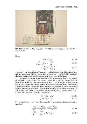
                             FIGURE 11.21: Picture of the complete circuit for LED control via the digital output of a PIC
                             microcontroller.


                             Hence,
                                                              i (s) = i (s)                    (11.93)
                                                              1
                                                                    2
                                                        Cs          −V (s)
                                                                       o
                                                             V (s) =                           (11.94)
                                                               i
                                                      R Cs + 1        R 2
                                                       1
                                                             V (s)     R Cs
                                                              o         2
                                                                  =−                           (11.95)
                                                             V (s)   R Cs + 1
                                                              i
                                                                       1
                             which shows that the new transfer function is a modified version of the differentiator. It not
                             only has a zero at the origin s = 0, but also has a pole at s =−1∕(R C). This added pole
                                                                                    1
                             eliminates the high noise amplification problem of the “pure” differentiator.
                                  In practice, an integral op-amp circuit typically includes a parallel resistor with the
                             capacitor (R in Figure 11.18). The reason for this is that a “pure” integrator adds a −90
                                       4
                             degree phase (phase lag) to the loop at all frequencies. If we could reduce that phase lag at
                             least at lower frequencies, it would improve the stability of the closed loop system. Hence,
                             a pure integrator may be modified with a resistor R in parallel with the capacitor in the
                                                                       4
                             feedback path to accomplish this. Let us show the new transfer function by derivation. Let
                             i (t) be the current across R , i (t) be the current across R , and i (t) be the current across
                                                                           2
                                                   1
                                                      2
                                                                                 3
                              1
                             C. From the same op-amp relations, it follows that
                                                          i (t) = i (t) + i (t)                (11.96)
                                                          1     2     3
                                                          i (s) = i (s) + i (s)                (11.97)
                                                          1     2     3
                             It is straightforward to show the relationships between currents, voltages, and resistors/
                             capacitor,
                                                 V (t)  0 − V (t)  d(0 − V (t))
                                                   i
                                                                          o
                                                             o
                                                      =         + C                            (11.98)
                                                  R 3      R 4         dt
                                                 V (s)  −V (s)
                                                  i
                                                           o
                                                      =       + Cs(−V (s))                     (11.99)
                                                                     o
                                                  R       R
                                                   3       4
   782   783   784   785   786   787   788   789   790   791   792