
Page 784 - Mechatronics with Experiments
P. 784
770 MECHATRONICS
GND
+V
OUT
IN
–V
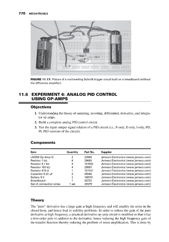
FIGURE 11.17: Picture of a noninverting Schmitt trigger circuit built on a breadboard (without
the difference amplifier).
11.6 EXPERIMENT 6: ANALOG PID CONTROL
USING OP-AMPS
Objectives
1. Understanding the theory of summing, inverting, differential, derivative, and integra-
tor op-amps.
2. Build a complete analog PID control circuit.
3. Test the input–output signal relation of a PID circuit (i.e., P-only, D only, I only, PD,
PI, PID versions of the circuit).
Components
Item Quantity Part No. Supplier
LM358 Op-Amp IC 3 23966 Jameco Electronics (www.jameco.com)
Resistor 1 kΩ 8 29663 Jameco Electronics (www.jameco.com)
Resistor 4.7 kΩ 4 107633 Jameco Electronics (www.jameco.com)
Resistor 100 kΩ 4 29997 Jameco Electronics (www.jameco.com)
Resistor 470 Ω 1 107537 Jameco Electronics (www.jameco.com)
Capacitor 0.22 μF 2 25540 Jameco Electronics (www.jameco.com)
Battery 9 V 2 198791 Jameco Electronics (www.jameco.com)
Breadboard 1 20722 Jameco Electronics (www.jameco.com)
Set of connection wires 1 set 20079 Jameco Electronics (www.jameco.com)
Theory
The “pure” derivative has a large gain at high frequency and will amplify the noise in the
closed loop, and hence lead to stability problems. In order to reduce the gain of the pure
derivative at high frequency, a practical derivative op-amp circuit is modified so that it has
a first-order pole in addition to the derivative, hence reducing the high frequency gain of
the transfer function thereby reducing the problem of noise amplification. This is done by