
Page 785 - Mechatronics with Experiments
P. 785
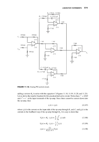
LABORATORY EXPERIMENTS  771
                                                            R = 220 Ω , 2.0 MΩ
                                                             4
                                                   R  = 330 kΩ  C = 0.22 μF
                                                    3
                                                                    +9 V
                                                                   –      1 kΩ
                                                                   +
                                                              4.7 kΩ  –9 V


                                100 kΩ      100 kΩ
                             V i
                                              +9 V
                                                     1 kΩ       1 kΩ
                                            –
                                                                                      1 kΩ
                                100 kΩ      +
                                                                 +9 V
                                              –9 V                      1 kΩ               +9 V
                             V ref                              –
                                         100 kΩ                 +                         – +      V
                                                                 –9 V                               o
                                                           1 kΩ                            –9 V
                                                                                      1 kΩ


                                                     C = 0.22 μF  R  = 4.7 kΩ
                                                              2
                                                                 +9 V
                                                  R  = 4.7 kΩ
                                                   1
                                                                –
                                                                +        1 kΩ
                                                                 –9 V
                                                      4.7 kΩ


                             FIGURE 11.18: Analog PID control circuit.


                             adding a resistor R in series with the capacitor C (Figures 11.18, 11.19, 11.20, and 11.21).
                                            1
                                                                                             +
                             Let us derive the transfer function for this practical derivative circuit. Notice that v = GND
                                  +
                                      −
                             and v = v at the input terminals of the op-amp. Since there cannot be current drawn into
                             the op-amp, then
                                                             i (t) = i (t)                     (11.87)
                                                                   2
                                                             1
                             where i (t) is the current on the input side of the op-amp through R and C, and i (t)isthe
                                                                                              2
                                                                                   1
                                   1
                             current on the feedback loop of the op-amp through R . It is easy to show that
                                                                        2
                                                                        t
                                                                    1
                                                    V (t) = R ⋅ i (t) +  C ∫  i (  )d          (11.88)
                                                                         1
                                                              1
                                                            1
                                                     i
                                                                       0
                                                                    1 1
                                                    V (s) = R ⋅ i (s) +  i (s)                 (11.89)
                                                     i      1  1       1
                                                                    C s
                                                             Cs
                                                    i (s) =       V (s)                        (11.90)
                                                                    i
                                                     1
                                                           R Cs + 1
                                                            1