
Page 780 - Mechatronics with Experiments
P. 780
766 MECHATRONICS
4. Connect an oscilloscope to the input and output of the low pass filter. Sweep the
frequency range of 10 Hz to 100 kHz and measure the output voltage at each selected
frequency, that is 10 Hz, 100 Hz, 1, 10, 50, 100 kHz. Create a table showing the ratio
V out
| | = |H( jw)| for the selected frequencies. Do the same for phase shift (phase
V in
angle) between V out ( jw) and V ( jw).
in
5. Use logarithmic scale to plot the amplitude response and phase angle of the filter
(Bode plot). Show |H( j )| over frequency. Mark in the 20 log |H( jw)| =−3dB
10
(equivalently, |H( jw)| = 0.707) cutoff frequency. Compare the experimental results
®
with analytical results obtained by plotting Equation 11.71 using MATLAB .
6. What is the attenuation of the filter per decade in the transition band (that is the slope
in log-log scale, 20 log |H( jw)| versus log w)?
10
10
7. Set up the function generator to produce a square wave with a frequencies of 100 Hz,
2.0 kHz, 10 kHz. Measure the output signal and make a sketch in your solution sheet.
Explain the result in terms of frequency content.
8. (Optional) If your digital storage oscilloscope is capable of taking FFT (Fast Fourier
Transforms), take the FFT of both the input signal and output signal. Discuss the
results. From the FFT of input and output signals, obtain the experimental transfer
function of the low pass filter circuit in the frequency domain. Discuss the frequency
response (the transfer function in the frequency domain, that this the ratio of FFT
of output signal to the FFT of the input signal) compared to the analytical transfer
function evaluated as a function of frequency.
9. (Optional) Discuss how you could take the FFT of the input and output signals using
the PIC microcontroller. (Hint: Use ADC channels 0 and 1 for input and output
signals. What is the limitation of the PIC microcontroller: available RAM memory
for data?)
10. (Optional) Repeat the same experiment for an active high pass filter.
11.5 EXPERIMENT 5: SCHMITT TRIGGER WITH VARIABLE
HYSTERESIS USING AN OP-AMP CIRCUIT
Objectives
1. Understanding the theory of the Schmitt trigger circuit (relay control with hysteresis)
and its applications.
2. Circuit design of a variable hysteresis Schmitt trigger circuit using op-amp.
3. Measuring the hysteresis band of the Schmitt trigger circuit.
4. Application of this circuit as a relay control (with hysteresis) for closed loop control
(i.e., as analog controller).
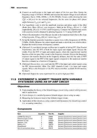
Components
Item Quantity Part No. Supplier
LM358 Op-Amp IC 2 23966 Jameco Electronics (www.jameco.com)
Potentiometer (2 kΩ) 2 41865 Jameco Electronics (www.jameco.com)
Resistor 4.7 kΩ 1 107633 Jameco Electronics (www.jameco.com)
Resistor 1 kΩ 5 29663 Jameco Electronics (www.jameco.com)
Battery 9 V 2 198791 Jameco Electronics (www.jameco.com)
Breadboard 1 20722 Jameco Electronics (www.jameco.com)
Set of connection wires 1 set 20079 Jameco Electronics (www.jameco.com)