Page 779 - Mechatronics with Experiments
P. 779

LABORATORY EXPERIMENTS  765


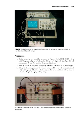
                             FIGURE 11.12: Picture of the experiment for a first-order active low pass filter: circuit on
                             breadboard and the oscilloscope.

                             Procedure

                                1. Design an active low pass filter as shown in Figures 11.11, 11.12, 11.13 with a
                                  cutoff frequency of f ≈ 1.9 kHz and a DC gain of |G DC | = 1. Use R = 820 kΩ
                                                                                            1
                                                   c
                                  and calculate R and C to meet the design specifications.
                                              2
                                2. Build up the circuit and power the op-amp with a 9-V battery or a DC power supply.
                                3. Set up the function generator to produce a sinusoidal wave with an amplitude of
                                  6 V (peak-to-peak). Adjust the offset voltage so that input excitation voltage range is
                                  within the DC power supply voltage range.


                                             GND
                                                   V–
                                                IN
                                                                 OUT


                                                          V+


                             FIGURE 11.13: Picture of the circuit of a first-order active low pass filter on the solderless
                             breadboard.
   774   775   776   777   778   779   780   781   782   783   784