
Page 159 - Servo Motors and Industrial Control Theory -
P. 159
154 9 The Choice and Comparison of Servo Motors
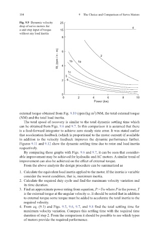
Fig. 9.9 Dynamic velocity 25
drop of servo motors for 4
a unit step input of torque 15
without any load inertia
8
W r (rpm / n - m) 6 4 1b 1a 2
1c
5
2 6
0
0 2 4 6 8 10
Power (kw)
external torque obtained from Fig. 9.10 (rpm/(kg m )/NM, the total external torque
2
(NM) and the total load inertia.
The total speed of recovery is similar to the total dynamic settling time which
can be obtained from Figs. 9.6 and 9.7. In this comparison it is assumed that there
is a feed-forward integrator to achieve zero steady state error. It was stated earlier
that acceleration feedback (which is proportional to the motor current) if available
in addition to the velocity feedback improves the dynamic performance further.
Figures 9.11 and 9.12 show the dynamic settling time due to rotor and load inertia
respectively.
By comparing these graphs with Figs. 9.6 and 9.7, it can be seen that consider-
able improvement may be achieved for hydraulic and AC motors. A similar trend of
improvement can also be achieved on the effect of external torque.
From the above analysis the design procedure can be summarized as
1. Calculate the equivalent load inertia applied to the motor. If the inertia is variable
consider the worst condition, that is, maximum inertia.
2. Calculate the required duty cycle and find the maximum velocity variation and
its time duration.
3. Find an approximate power rating from equation, P:=Tω where P is the power, T
is the external torque at the angular velocity ω. It should be noted that in addition
to external torque some torque must be added to accelerate the total inertia to the
required velocity.
4. From eq. (9.1) and Figs. 9.5, 9.6, 9.7, and 9.8 find the total settling time for
maximum velocity variation. Compare this settling time with the required time
duration of step 2. From the comparison it should be possible to see which types
of motors provide the required performance.