
Page 154 - Servo Motors and Industrial Control Theory -
P. 154
9.3 Comparison of Results and Design Procedure 149
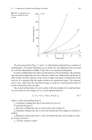
Fig. 9.4 A comparison of 200 × 10 -3
the rotor inertia of servo 1
motors
160
Rotor Inertia (kg-m 2 ) 120 2
80
40 5
3 6
4
0
0 2 4 6 8 10
Power (kw)
The data presented in Figs. 9.3 and 9.4 is information obtained from a number of
manufactures. The reader must keep an eye on the new development in this area and
try to fit the information available in the above two mentioned diagrams.
In order to differentiate the effect of load inertia on the performance, the dynamic
and saturated settling time are first obtained without any additional load inertia. In
other words, first the response of the motor to large step input is studied and in this
exercise it is assumed that the motor produces its maximum torque. This assump-
tion is only valid when the maximum torque is used for a short period of time to
avoid overheating in the circuitry.
The overall settling time of a servo motor with rotor inertia of ( I ) and load iner-
tia of ( I ) and velocity change of ( ω ) can be approximated as r
l c
t : = t + I ·t +ω ·t +ω ·I ·t (9.1)
a r1 1 r 2 c s1 c 1 s2
where t is the total settling time (s)
a
t is dynamic settling time due to the inertia of rotor (s)
r1
I Load inertia (kg m )
2
1
t Dynamic settling time due to a unit load inertia (s/(kg m )
2
r2
t Saturated settling time due to the rotor inertia and unit change in velocity (s/
s1
(rad/s))
t Saturated settling time due to a unit of load inertia and a unit change in veloc-
s2
ity (s/(kg m )/(rad/s)
2
ω velocity variation (rad/s)
c