
Page 84 - Servo Motors and Industrial Control Theory -
P. 84
4.6 DC Servo Motors for Very High Performance Requirements 77
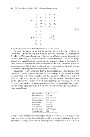
0 1 0 0 0
A A A 0 0
2 3 1
A:= 0 0 0 1 0
A 0 A A A
8 7 6 5
A 0 0 A A
10 12 11
(4.20)
0 0
0 A
4 θ
B:= 0 0 U := i
T
0 0 1
A 0
9
Note that the usual brackets for the matrices are not shown.
The reader is warned to see that the subscript of J and T in Eq. (4.17) is the
lower case L. It can be seen that there are five state equations. The subscript of
C in Eq. (4.17) is again lower case L showing the effect of viscous friction in the
load side and C in Eq. (4.17) is the viscous friction at the motor side. At the design
stage, the two coefficients of viscous damping may not be known. For simplicity,
these two coefficients may be set to zero to consider the worst conditions. When the
system is designed the friction coefficients can be measured and the analysis may
be improved a better performance design specifications.
Equation (4.17) now is the form that was described in Chap. 4. It is desirable first
to study the open loop system equation. For this, it is required that numerical values
are substituted in the system equation and the eigenvalues of the system matrix A
gives the roots of the characteristic equation. From the position of the eigenvalues
on the s-plane a state variable feedback control strategy can be studied. The reader
is encouraged to derive the system equation by doing the manipulations to ensure
that the system equation is correct. A DC servo motor with the following specifica-
tions is considered:
Arm resistance 0.36 Ω
Arm inductance 0.88 mH
Voltage constant 0.83 V/(rad/s)
Torque constant 0.83 Nm/amp
Rated torque 17.5 Nm
Max torque 132 Nm
Max. velocity 1420 rpm
The rotor inertia 0.0078 kg m 2
2
Controller gain 100
It can be seen that the maximum torque, which is available for a short period of
time, is much larger than the rated torque, which can be used continuously. It can be
proved by the energy consideration that torque and voltage constants are equal for