
Page 81 - Servo Motors and Industrial Control Theory -
P. 81
74 4 Electrical DC Servo Motors
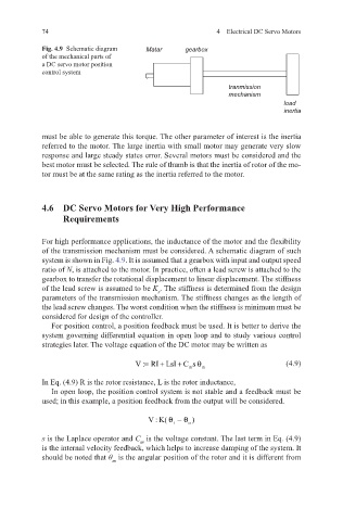
Fig. 4.9 Schematic diagram Matar gearbox
of the mechanical parts of
a DC servo motor position
control system
tranmission
mechanism
load
inertia
must be able to generate this torque. The other parameter of interest is the inertia
referred to the motor. The large inertia with small motor may generate very slow
response and large steady states error. Several motors must be considered and the
best motor must be selected. The rule of thumb is that the inertia of rotor of the mo-
tor must be at the same rating as the inertia referred to the motor.
4.6 DC Servo Motors for Very High Performance
Requirements
For high performance applications, the inductance of the motor and the flexibility
of the transmission mechanism must be considered. A schematic diagram of such
system is shown in Fig. 4.9. It is assumed that a gearbox with input and output speed
ratio of N, is attached to the motor. In practice, often a lead screw is attached to the
gearbox to transfer the rotational displacement to linear displacement. The stiffness
of the lead screw is assumed to be K . The stiffness is determined from the design
s
parameters of the transmission mechanism. The stiffness changes as the length of
the lead screw changes. The worst condition when the stiffness is minimum must be
considered for design of the controller.
For position control, a position feedback must be used. It is better to derive the
system governing differential equation in open loop and to study various control
strategies later. The voltage equation of the DC motor may be written as
V : RI LsI C s = + + θ (4.9)
m m
In Eq. (4.9) R is the rotor resistance, L is the rotor inductance,
In open loop, the position control system is not stable and a feedback must be
used; in this example, a position feedback from the output will be considered.
V : K( θ −θ )
o
i
s is the Laplace operator and C is the voltage constant. The last term in Eq. (4.9)
m
is the internal velocity feedback, which helps to increase damping of the system. It
should be noted that θ is the angular position of the rotor and it is different from
m