
Page 77 - Servo Motors and Industrial Control Theory -
P. 77
70 4 Electrical DC Servo Motors
T 1
K 1 I T 1 ω m
ω i s R K t Js + C m
C m
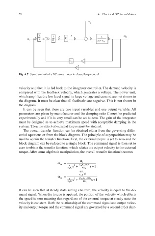
Fig. 4.7 Speed control of a DC servo motor in closed loop control
velocity and then it is fed back to the integrator controller. The demand velocity is
compared with the feedback velocity, which generates a voltage. The power unit,
which amplifies the low level signal to large voltage and current, are not shown in
the diagram. It must be clear that all feedbacks are negative. This is not shown in
the diagram.
It can be seen that there are two input variables and one output variable. All
parameters are given by manufacturer and the damping ratio C must be predicted
experimentally and if it is very small can be set to zero. The gain of the integrator
must be designed as to achieve maximum speed with acceptable damping in the
system. Then the effect of external torque must be studied.
The overall transfer function can be obtained either from the governing differ-
ential equations or from the block diagram. The principle of superposition may be
used to obtain the transfer function. First, the external torque is set to zero and the
block diagram can be reduced to a single block. The command signal is then set to
zero to obtain the transfer function, which relates the output velocity to the external
torque. After some algebraic manipulation, the overall transfer function becomes
ω
ω = i
m R s + C K t + CR +
2
m
K K KK t s1
t
− RT
1 s
ω = KK
t
m R s + (C K t + CR) +
2
m
K K KK t s1
t
It can be seen that at steady state setting s to zero, the velocity is equal to the de-
mand signal. When the torque is applied, the portion of the velocity which effects
the speed is zero meaning that regardless of the external torque at steady state the
velocity is constant. Both the relationship of the command signal and output veloc-
ity and output torque and the command signal are governed by a second order char-