
Page 78 - Servo Motors and Industrial Control Theory -
P. 78
4.4 DC Servo Motors in Open and Closed Loop Velocity Control 71
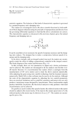
Fig. 4.8 A proportional +
and integral control K + K 2
1
s
ω i –
acteristic equation. The behavior of this kind of characteristic equation is governed
by a natural frequency and a damping ratio.
The readers are encouraged to derive the above transfer functions by both meth-
od of block diagram reduction using the principle of superposition and directly from
the governing differential equations to find that the above calculations are correct.
The characteristic equation as discussed in the previous chapters gives the natural
frequency and damping ratio as
K
ω= K
:
n t
R
K C K + CR
ξ =
: 0.5 K m t
t
R KK
t
It can be seen that as K is increased, the speed of response increases and the damp-
ing ratio reduces. The designer has to make a compromise between speed of re-
sponse and the damping ratio.
In the above example, only an integral control was used, the readers are encour-
aged to study the effect of adding a proportional controller to the integral control.
The block diagram of the control unit becomes (Fig. 4.8)
In this example, there are two parameters to adjust and a better performance
can be achieved. The readers are encouraged to do the analysis and find the over-
all transfer function. It is recommended that readers obtain a catalogue from the
manufacturers of DC servo motors and to study the above analysis numerically.
After adjusting the gains using state variable technology find the transient response
numerically. MathCAD or other software may be used to do the analysis. Although
the roots of the characteristic equation by adjusting the two control parameters,
there are practical limitations such as amplifier saturation and power unit can only
produce a maximum torque designed by manufacturer. These nonlinearities might
produce instability. In practice, the theoretical analysis is only guidance what kind
of performance can be achieved.
If a gearbox is used to reduce the speed of motor, the referred inertia to the motor
should be added to the motor inertia. If the input to the output speed ratio is N, the
2
referred inertia to the motor may be shown to be as J /N . The readers are encour-
l
aged to prove this.