
Page 75 - Untitled-1
P. 75
54 PROJECT INITIATION TECHNIQUES
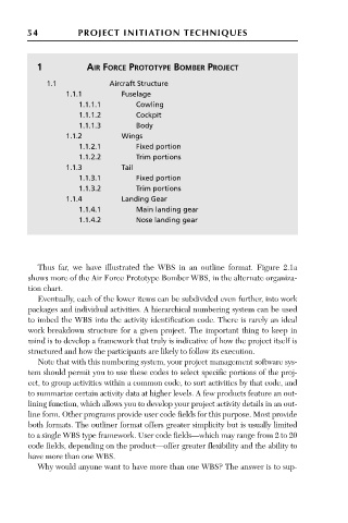
1 AIR FORCE PROTOTYPE BOMBER PROJECT
1.1 Aircraft Structure
1.1.1 Fuselage
1.1.1.1 Cowling
1.1.1.2 Cockpit
1.1.1.3 Body
1.1.2 Wings
1.1.2.1 Fixed portion
1.1.2.2 Trim portions
1.1.3 Tail
1.1.3.1 Fixed portion
1.1.3.2 Trim portions
1.1.4 Landing Gear
1.1.4.1 Main landing gear
1.1.4.2 Nose landing gear
Thus far, we have illustrated the WBS in an outline format. Figure 2.1a
shows more of the Air Force Prototype Bomber WBS, in the alternate organiza-
tion chart.
Eventually, each of the lower items can be subdivided even further, into work
packages and individual activities. A hierarchical numbering system can be used
to imbed the WBS into the activity identification code. There is rarely an ideal
work breakdown structure for a given project. The important thing to keep in
mind is to develop a framework that truly is indicative of how the project itself is
structured and how the participants are likely to follow its execution.
Note that with this numbering system, your project management software sys-
tem should permit you to use these codes to select specific portions of the proj-
ect, to group activities within a common code, to sort activities by that code, and
to summarize certain activity data at higher levels. A few products feature an out-
lining function, which allows you to develop your project activity details in an out-
line form. Other programs provide user code fields for this purpose. Most provide
both formats. The outliner format offers greater simplicity but is usually limited
to a single WBS type framework. User code fields—which may range from 2 to 20
code fields, depending on the product—offer greater flexibility and the ability to
have more than one WBS.
Why would anyone want to have more than one WBS? The answer is to sup-