
Page 496 - Icon Ridge Industrial Tools Catalog
P. 496
Lathe tools \ Technical introduction–turning - ISO turning
Determination of the correct design for lathing
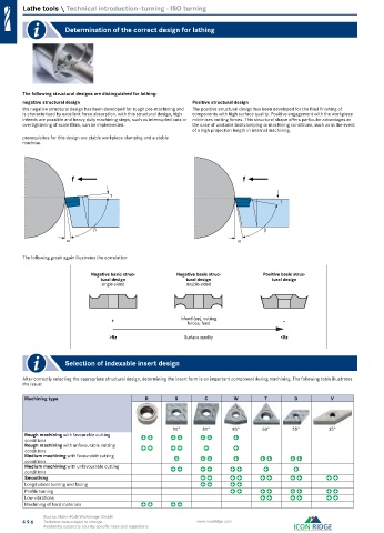
The following structural designs are distinguished for lathing:
negative structural design Positive structural design
the negative structural design has been developed for rough pre-machining and The positive structural design has been developed for the final finishing of
is characterised by excellent force absorption. with this structural design, high components with high surface quality. Positive engagement with the workpiece
infeeds are possible and heavy duty machining steps, such as interrupted cuts or minimises cutting forces. This structural shape offers particular advantages in
overtightening of scale films, can be implemented. the case of unstable tool clamping or machining conditions, such as in the event
of a high projection length in internal machining.
prerequisites for this design are stable workpiece clamping and a stable
machine.
f f
The following graph again illustrates the correlation:
Negative basic struc- Negative basic struc- Positive basic struc-
tural design tural design tural design
single-sided double-sided
+ Infeed (ap), cutting –
forces, feed
>Rz Surface quality <Rz
Selection of indexable insert design
After correctly selecting the appropriate structural design, determining the insert form is an important component during machining. The following table illustrates
the issue:
Machining type R S C W T D V
90° 80° 80° 60° 55° 35°
Rough machining with favourable cutting
conditions
Rough machining with unfavourable cutting
conditions
Medium machining with favourable cutting
conditions
Medium machining with unfavourable cutting
conditions
Smoothing
Longitudinal turning and facing
Profile turning
Low vibrations
Machining of hard materials
Source: Hahn+Kolb Werkzeuge GmbH
496 Technical data subject to change. www.iconridge.com
Availability subject to country specific rules and regulations.