
Page 560 - Icon Ridge Industrial Tools Catalog
P. 560
Lathe tools \ Technical information/standard sheet, ISO holder
clamp holder for turning for outside machining
clamp system, dimensions and tolerances
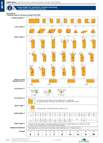
Designations
Clamping holder for turning according to DIN 4983
Clamping system ➀
Insert shape ➁ 55°
K
Holder shape ➂
Clearance angle
indexable insert ➃
Cut direction ➄
R = right L = left N = neutral
Cut direction ➅
As basic number, the height of the cutter edge h in mm is indicated.
For clamping holders, the height of the cutter edge h equals the shank height.
Shank width ➆
Clamping holder: Indication of the shank width b in mm.
Holder length ➇ A B C D E F G H J K L M N
mm 32 40 50 60 70 80 90 100 110 125 140 150 160
P Q R S T U V W X Y –
mm 170 180 200 250 300 350 400 450 500
Cutter length ➈ Indication of the cutter length in mm without decimal point, in case of one-digit numerals with leading 0 (e. g. 08).
In case of round indexable inserts, the diameter is always indicated.
Additional indications These indications do not form part of the standard and are facultative, e. g. "-U" stands: with shim.
Example ➀ ➁ ➂ ➃ ➄ ➅ ➆ ➇ ➈
S C L C R 16 16 H 09
Source: Hahn+Kolb Werkzeuge GmbH
560 Technical data subject to change. www.iconridge.com
Availability subject to country specific rules and regulations.