
Page 677 - Icon Ridge Industrial Tools Catalog
P. 677
Lathe tools \ Technical introduction - knurling
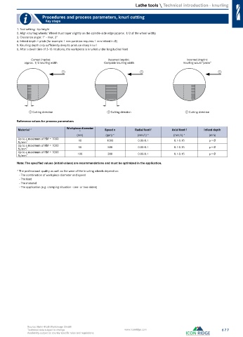
Procedures and process parameters, knurl cutting
Key steps
1. Tool setting - tip height
2. Align knurling wheels: Wheel must taper slightly on the spindle-side edge (approx. 1/3 of the wheel width)
3. Clearance angle: 1° - max. 3°
4. Infeed depth = pitch (for example 1 mm partition requires 1 mm infeed in Ø)
5. Knurling depth only sufficiently deep to produce sharp knurl
6. After a dwell time of 3-10 rotations, the workpiece is knurled under longitudinal feed
Correct imprint: Incorrect imprint: Incorrect imprint:
approx. 1/3 knurling width Complete knurling width Knurling would “press”
1 1 1
① Cutting direction ① Cutting direction ① Cutting direction
Reference values for process parameters
Material * Workpiece diameter Speed n Radial feed f Axial feed f Infeed depth
*
(mm) (rpm) * (mm/r) * (mm/r) * (mm)
Up to a maximum of RM = 1000 10 1000 0.08-0.1 0.1-0.15 p = Ø
N/mm 2
Up to a maximum of RM = 1000 50 500 0.08-0.1 0.1-0.15 p = Ø
N/mm 2
Up to a maximum of RM = 1000 100 300 0.08-0.1 0.1-0.15 p = Ø
N/mm 2
Note: The specified values (initial values) are recommendations and must be optimized in the application.
* The professional quality as well as the wear of the knurling wheels depend on:
- The combination of workpiece diameter and speed
- The feed
- The material
- The application (e.g. clamping situation - one- or two-sided)
Source: Hahn+Kolb Werkzeuge GmbH
Technical data subject to change. www.iconridge.com 677
Availability subject to country specific rules and regulations.