
Page 5 - PD Experience on 3-5kV
P. 5
Six months later in July 2007, the results were now +909mV/-1880mV with a strong negative
predominance indicative of internal voids due to a potentially damaged interturn insulation. Three
months later in Oct 2007, the levels were still increasing at +1120mV/-2317mV. The motor was
removed from service and shipped to a rewind shop. At the rewind shop, it passed the surge test and it
passed the DC hipot at 9.3kV. During the AC hipot, at 2000V the PD was visible and audible,
increasing in intensity at 3000V and finally catching on fire at 4000V.
• A case study was presented about a 3.3kV induction motors for one utility. [13] The findings were:
• “Original manufactured machines (some of them older than 20 years), have PD values lower
than 90 mV. Most of these machines are operating at low temperatures and appear to be in
good condition.
• Recently rewound machines displayed high PD levels and are suspected of going through
poor VPI processes. We expect these PD levels to decrease after going through normal
thermal cycling.
• Contamination levels can successfully be monitored with PD equipment.”
2.2 SINGLE-ENDED INSTALLATION
For each phase, one PD sensor, or EMC, is mounted at the motor,
generator, switchgear or transformer terminals and is referred to as the
“machine” coupler. This EMC measures the partial discharge (PD)
originating within the machine stator winding or high voltage
apparatus. It is desirable that there be no feeders, splits, CTs, PTs, or
similar devices located between the machine terminals and the
machine sensor on any given phase. The presence of such can lead to
signal distortion and imperfect noise reduction.
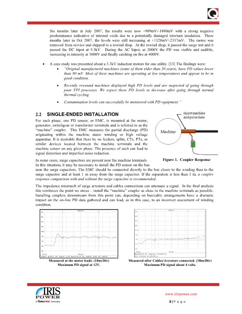
In some cases, surge capacitors are present near the machine terminals. Figure 1. Coupler Response
In this situation, it may be necessary to install the PD sensor on the bus
near the surge capacitors. The EMC should be connected directly to the bus closer to the winding than to the
surge capacitor and at least 1 m away from the surge capacitor. If the separation is less than 1 m, a coupler
response comparison with and without the surge capacitor is recommended.
The impedance mismatch of surge arrestors and cables connections can attenuate a signal. In the final analysis
this reinforces the point we stress – install the “machine” coupler as close to the machine terminals as possible.
Installing couplers downstream from this point can, depending on bus/cable arrangements have a dramatic
impact on the on-line PD data gathered and can lead, as in this case, to an incorrect assessment of winding
condition.
Measured at the motor leads. (10ns/Div) Measured after Cables/Arrestors connected. (10ns/Div)
Maximum PD signal at 12V. Maximum PD signal about 4 volts.
www.irispower.com
3 | P age