
Page 10 - PD Experience on 3-5kV
P. 10
insulation discoloration visual inspection (Asphaltic mica)
3.5 COIL MOVEMENT FAILURE
3.5.1 Impact:
If properly installed, the wedges and side packing should prevent winding looseness. However, some
insulation resins shrink when they are cured or thermally aged, coils may get smaller and so become loose in
the slot. Also, some of the wedging and packing materials may become brittle and shrink over time, allowing
the coils to become loose. In the presence of oil, side packing and ripple springs will soften faster because of
the lubricating medium.
When windings become loose in the slot, the immediate problem is that, if left unattended, the looseness and
vibration will quickly allow the laminated rough stator core surface to damage the semi-conductive coating on
the surface of the coils. Damaged coil surfaces create discontinuities on the surface and allow voltage stresses
to build up across these isolated locations, or between these and the stator core. If the voltage stress exceeds
the electrical breakdown point of the gas medium, a discharge will occur. See Case Study 5.3.
3.5.2 Probability:
In a global VPI, coil movement normally has a low probability; however, when deterioration of the semi
conductive coating occurs the probability increases due to the chemical attack on the resin securing the
wedges in place.
3.5.3 Risk to the winding:
Eventually, a ladder-effect develops where the groundwall is thinner at the point of contact with the core, but
maintains normal thickness at the core air vents. Though the absolute time between detection and failure is
unknown, it can be as short as two years in many thermoset (hard) windings, especially those with a high
electric stress across the groundwall.
Bipolar C2 Bipolar C2
0 to 3.16 pps 3.16 to 10 pps 10 to 31.6 pps 31.6 to 100 pps 0 to 3.16 pps 3.16 to 10 pps 10 to 31.6 pps 31.6 to 100 pps
100 to 316 pps 316 to 1000 pps > 1000 pps Subset 8 100 to 316 pps 316 to 1000 pps > 1000 pps Subset 8
750 750 750 750
500 500 500 500
250 250 250 250
Pulse Magnitude [mV]
Pulse Magnitude [mV]
-250 0 0 -250 -250 0 0 -250
-500 -500 -500 -500
-750 -750 -750 -750
0 45 90 135 180 225 270 315 360 0 45 90 135 180 225 270 315 360
Phase Angle [deg] Phase Angle [deg]
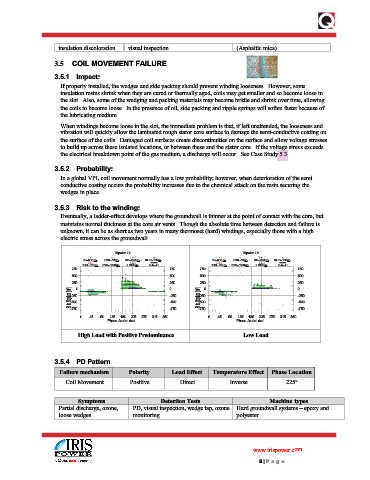
High Load with Positive Predominance Low Load
3.5.4 PD Pattern
Failure mechanism Polarity Load Effect Temperature Effect Phase Location
Coil Movement Positive Direct Inverse 225°
Symptoms Detection Tests Machine types
Partial discharge, ozone, PD, visual inspection, wedge tap, ozone Hard groundwall systems – epoxy and
loose wedges monitoring polyester
www.irispower.com
8 | P age