
Page 11 - Concrete-Technology-Interacted_Book_Prof-MIK_Neat
P. 11
2/6 Plastic and thermal cracking
Bleeding
(a) Initiation
Crack
Void
Bleeding
(b) After a few hours
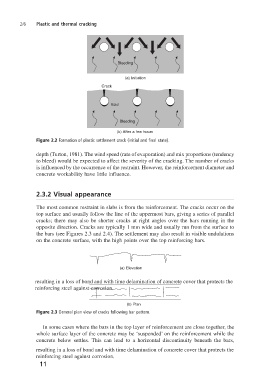
Figure 2.2 Formation of plastic settlement crack (initial and final state).
depth (Turton, 1981). The wind speed (rate of evaporation) and mix proportions (tendency
to bleed) would be expected to affect the severity of the cracking. The number of cracks
is influenced by the occurrence of the restraint. However, the reinforcement diameter and
concrete workability have little influence.
2.3.2 Visual appearance
The most common restraint in slabs is from the reinforcement. The cracks occur on the
top surface and usually follow the line of the uppermost bars, giving a series of parallel
cracks; there may also be shorter cracks at right angles over the bars running in the
opposite direction. Cracks are typically 1 mm wide and usually run from the surface to
the bars (see Figures 2.3 and 2.4). The settlement may also result in visible undulations
on the concrete surface, with the high points over the top reinforcing bars.
(a) Elevation
resulting in a loss of bond and with time delamination of concrete cover that protects the
reinforcing steel against corrosion.
(b) Plan
Figure 2.3 General plan view of cracks following bar pattern.
In some cases where the bars in the top layer of reinforcement are close together, the
whole surface layer of the concrete may be ‘suspended’ on the reinforcement while the
concrete below settles. This can lead to a horizontal discontinuity beneath the bars,
resulting in a loss of bond and with time delamination of concrete cover that protects the
reinforcing steel against corrosion.
11