
Page 1206 - Master Catalog 2017, Inch
P. 1206
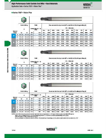
High-Performance Solid Carbide End Mills • Hard Materials
Application Data • Series 7S5F • Vision Plus ™
Series 7S5F • Vision Plus
Profile Milling TiAlN Recommended feed per tooth (IPT = inch/th) for 3D milling/profiling (A)
Cutting Speed — vc D1 — Diameter
A
SFM frac. 1/8 5/32 3/16 1/4 5/16 3/8 7/16 1/2 5/8 3/4
Material
Group ap ae min max dec. .1250 .1563 .1875 .2500 .3125 .3750 .4375 .5000 .6250 .7500
3 0.5 x D 0.5 x D 910 – 1210 IPT .0031 .0039 .0048 .0065 .0084 .0098 .0112 .0124 .0147 .0166
P
4 0.5 x D 0.5 x D 680 – 1130 IPT .0029 .0036 .0044 .0059 .0075 .0088 .0099 .0110 .0129 .0145
1 0.5 x D 0.5 x D 600 – 1060 IPT .0029 .0036 .0044 .0059 .0075 .0088 .0099 .0110 .0129 .0145
2 0.5 x D 0.5 x D 530 – 910 IPT .0022 .0027 .0033 .0044 .0056 .0066 .0074 .0082 .0096 .0107
H
3 0.5 x D 0.5 x D 450 – 680 IPT .0017 .0021 .0026 .0035 .0044 .0052 .0059 .0066 .0078 .0089
4 0.5 x D 0.5 x D 380 – 530 IPT .0011 .0014 .0017 .0023 .0030 .0035 .0039 .0044 .0052 .0058
High-Performance Solid Carbide End Mills Material Profile Milling Cutting Speed — vc frac. .1250 .1563 .1875 .2500 D1 — Diameter .4375 .5000 .6250 .7500
Recommended feed per tooth (IPT = inch/th) for 3D milling/profiling (A)
TiAlN
A
SFM
3/16
5/8
5/32
1/4
5/16
3/8
7/16
3/4
1/2
1/8
ap
max
dec.
ae
min
.3750
Group
.3125
P
.0025
.0069
.0077
.0090
.0101
980
590
.0020
IPT
0.1 x D
.0061
.0030
.0041
0.1 x D
.0052
.0030
.0101
.0041
.0090
.0061
.0069
.0025
.0077
IPT
.0052
.0020
520
0.1 x D
0.1 x D
920
.0031
.0039
.0052
.0019
.0023
790
.0057
0.1 x D
IPT
460
.0046
.0067
0.1 x D
.0075
.0015
2 3 4 1 0.1 x D 0.1 x D 790 – – – – 1050 IPT .0022 .0027 .0033 .0046 .0059 .0069 .0078 .0087 .0102 .0116
H
3 0.1 x D 0.1 x D 390 – 590 IPT .0012 .0015 .0018 .0024 .0031 .0036 .0041 .0046 .0054 .0062
4 0.1 x D 0.1 x D 330 – 460 IPT .0008 .0010 .0012 .0016 .0021 .0024 .0027 .0031 .0036 .0041
Profile Milling TiAlN Recommended feed per tooth (IPT = inch/th) for 3D milling/profiling (A)
Cutting Speed — vc D1 — Diameter
A
SFM frac. 1/8 5/32 3/16 1/4 5/16 3/8 7/16 1/2 5/8 3/4
Material
Group ap ae min max dec. .1250 .1563 .1875 .2500 .3125 .3750 .4375 .5000 .6250 .7500
3 0.2 x D 0.2 x D 510 – 680 IPT .0009 .0012 .0014 .0020 .0025 .0030 .0034 .0038 .0044 .0050
P
4 0.2 x D 0.2 x D 380 – 640 IPT .0009 .0011 .0013 .0018 .0023 .0027 .0030 .0033 .0039 .0044
1 0.2 x D 0.2 x D 340 – 600 IPT .0009 .0011 .0013 .0018 .0023 .0027 .0030 .0033 .0039 .0044
2 0.2 x D 0.2 x D 300 – 510 IPT .0007 .0008 .0010 .0013 .0017 .0020 .0022 .0025 .0029 .0032
H
3 0.2 x D 0.2 x D 260 – 380 IPT .0005 .0006 .0008 .0011 .0013 .0016 .0018 .0020 .0024 .0027
4 0.2 x D 0.2 x D 210 – 300 IPT .0003 .0004 .0005 .0007 .0009 .0010 .0012 .0013 .0016 .0018
NOTE: Lower value of cutting speed is used for high stock removal applications or for higher hardness (machinability) within group.
Higher value of cutting speed is used for finishing applications or for lower hardness (machinability) within group.
For better surface finish, reduce feed per tooth.
Above parameters are based on ideal conditions. For smaller taper machining centers, please adjust parameters on diameters >1/2".
M150 widia.com
M150 M151 Mi h REBRANDO
V
WID M
i
Hi hP f
16 S lidE dMilli
L WID_Master16_SolidEndMilling_HighPerformance_M150_M151_Minch_REBRAND.indd 150 b 19 20155 10PM 10/29/15 2:10 PM