
Page 557 - Master Catalog 2017, Inch
P. 557
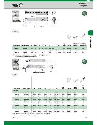
TopGroove ™
Boring Bars
Necked steel shank
with through coolant.
Right-hand toolholder shown.
A-NE-1
Grooving and Cut-Off
gage socket-head wrench size
order number catalog number D D min D2 L1 L2 F A CS insert clamp cap screw clamp screw
right hand
3632121 A06NER1 .375 .440 .312 6 1.250 .258 .125 — N.1L CM109 S304 5/64
3632119 A08NER1 .500 .440 .310 8 1.290 .258 .094 1/16-27 NPT N.1L CM109 S304 5/64
3632148 A10NER1 .625 .800 — 10 — .406 — 1/8-27 NPT N.1L CM109 S304 5/64
NOTE: Minimum bore capability varies with depth of groove. See page E92 for details.
F dimension measured over sharp point of insert.
Steel shank with
through coolant.
Right-hand tool holder shown.
A-NS
hex/
gage clamp Torx
order number catalog number D D min L1 F CS insert clamp screw Plus
right hand
3632129 A16TNSR3 1.000 2.250 12.000 .640 1/4-18 NPT N.3R CM72LP S2112 25 IP
3632135 A20UNSR3 1.250 2.250 14.000 .765 1/4-18 NPT N.3R CM72LP S2112 25 IP
3632134 A24UNSR3 1.500 2.250 14.000 .890 1/4-18 NPT N.3R CM72LP S2112 25 IP
3637516 A28UNSR3 1.750 2.250 14.000 1.015 1/4-18 NPT N.3R CM72LP S2112 25 IP
3632160 A32VNSR3 2.000 2.375 16.000 1.281 1/4-18 NPT N.3R CM72LP S2112 25 IP
3637513 A40VNSR3 2.500 2.875 16.000 1.531 1/4-18 NPT N.3R CM72LP S2112 25 IP
left hand
3632137 A16TNSL3 1.000 2.250 12.000 .640 1/4-18 NPT N.3L CM73LP S2112 25 IP
3637495 A20UNSL3 1.250 2.250 14.000 .765 1/4-18 NPT N.3L CM73LP S2112 25 IP
3637488 A24UNSL3 1.500 2.250 14.000 .890 1/4-18 NPT N.3L CM73LP S2112 25 IP
3637502 A32VNSL3 2.000 2.375 16.000 1.281 1/4-18 NPT N.3L CM73LP S2112 25 IP
NOTE: Minimum bore capability varies with depth of groove. See page E92 for details.
F dimension measured over sharp point of insert.
widia.com E85
b 92015310PM
WID_Master16_Turning_Grooving&CutOff_E084_E085_Minch_REBRAND.indd 85 L V i WID M 16 T i G i &C Off E084 E085 Mi h REBRANDN 11/10/15 11:14 AM