
Page 906 - Master Catalog 2017, Inch
P. 906
™
Slotting Mills • M900 Series
Assembly and Operating Instructions
Assembly and Operating Instructions
Slotting Mills
1. General
The runout tolerance of the milling cutter has a decisive effect on the quality of workpieces and the life cycle of tools. Proper tool fi tting and the precise
axial setting of the milling insert are essential for a successful application and optimum results. One key requirement for assembly and setting work is that
all components are clean. Bearing surfaces must be free from grease, and only the threads of indexable insert clamping screws and double threaded screws
of clamping and adjusting wedges should be lubricated with copper grease. The indexable inserts should be inserted in the cleaned insert seats so that they
are positioned correctly on the bearing surfaces. The indexable insert clamping screws should be tightened with the specifi ed torque.
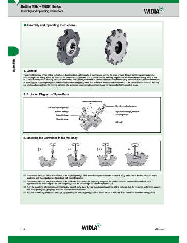
2. Exploded Diagram of Spare Parts
Double threaded screws
Right-hand adjusting wedge
Left-hand adjusting wedge
Left-hand cartridge Right-hand cartridge, complete
Clamping wedge
Indexable insert
Clamping screw
Mill body
3. Mounting the Cartridges in the Mill Body
3.1 3.2 3.3 3.4
3.1 Turn double threaded screw 1 clockwise in the adjusting wedge. Then insert both parts in the slot in the mill body and turn the double threaded screw
clockwise until the adjusting wedge is fl ush with the milling cutter.
3.2 Turn double threaded screw 3 clockwise in the mill body. Then mount the clamping wedge on the double threaded screw and screw both parts
together until the lower edge of the clamping wedge is at the same height as the chip space runout.
3.3 Push the top of the fully assembled cartridge into the mill body using the rear bearing surface of the milling cutter so that the cartridge slot makes contact
with the adjusting wedge spring. Ensure a perfect axial/radial surface.
3.4 Secure the correctly positioned cartridge by tightening the clamping wedge with a preset torque of MApre = 1 Nm to set the runout or cutting width.
J32 widia.com
Mill J032 J033 Mi h REBRANDN
i
Sl
i
V
WID M
bl MIlli
16 I d
L WID_Master16_IndexableMIlling_SlottingMills_J032_J033_Minch_REBRAND.indd 32 b 9 20155 43PM 11/10/15 10:34 AM