
Page 907 - Master Catalog 2017, Inch
P. 907
™
Slotting Mills • M900 Series
Assembly and Operating Instructions
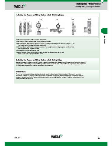
4. Setting the Runout for Milling Cutters with 2–3 Cutting Edges
4.1 4.2 4.3 4.4 4.5
Slotting Mills
4.1 Possible interpretations of the measuring dimension C.
4.2 Set gage to desired measurement C using gage blocks set to 0.
4.3 Set cartridge to ~0,1mm before fi nal measurement. Clamping wedge is tightened with torque MApre = 1 Nm.
Then briefl y loosen clamping wedge and tighten again.
4.4 Set cartridge to 0,02mm before fi nal measurement. Then briefl y loosen clamping wedge so that the contact
surfaces can level out. Tighten clamping.
4.4 Wedge again with torque MApre = 1 Nm.
4.5 Adjust cartridge to fi nal measurement. Tighten clamping wedge with torque MA = 4 Nm.
Check runout of the fully adjusted milling cutter.
5. Setting the Runout for Milling Cutters with 3 Cutting Edges
The cutting widths for milling cutters with 3 cutting edges are set using purpose-designed optical tool presetting equipment. Note that
the projection of the cartridges from the mill body must be almost exactly the same on both sides. The sequence of steps required for
setting the cartridge is identical to those for tools with 2 cutting edges.
ATTENTION:
At each tool adjustment, the body, cartridges, indexable inserts, and spare parts must be checked and replaced if necessary.
Before each tool use, the clamping and double threaded screws must be tightened with the specifi ed torque. The tools must only
be used in accordance with their function. We accept no liability for their improper use. Changes of any kind and/or printing errors
are not valid grounds for claims.
widia.com J33
b 92015543PM
WID_Master16_IndexableMIlling_SlottingMills_J032_J033_Minch_REBRAND.indd 33 L V i WID M 16 I d bl MIlli Sl i Mill J032 J033 Mi h REBRANDN 11/10/15 10:34 AM