Page 975 - Master Catalog 2017, Inch
P. 975

Copy Mills • M170  Series
                                                                                                              ™
                                                                                      Additional Application Advice • RD12T3..


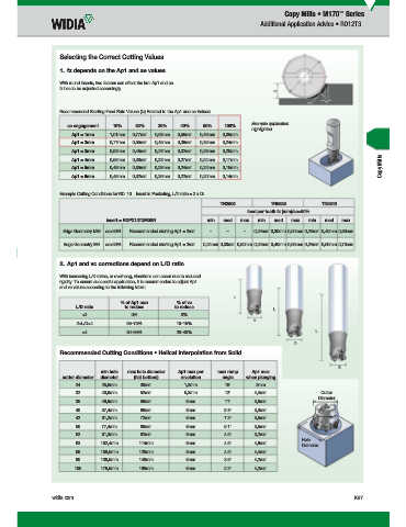
                      Selecting the Correct Cutting Values
                      1.  fz depends on the Ap1 and ae values

                      With round inserts, two factors can affect the hm: Ap1 and ae.
                    fz has to be adjusted accordingly.


                      Recommended Starting Feed Rate Values (fz) Related to the Ap1 and ae Values:
                                                                                    Example application
                       ae engagement  10%    20%    30%    40%    50%    100%
                                                                                  highlighted.
                        Ap1 = 1mm   1,01mm  0,77mm  0,63mm  0,55mm  0,49mm  0,35mm
                        Ap1 = 2mm   0,77mm  0,55mm  0,45mm  0,39mm  0,35mm  0,24mm
                        Ap1 = 3mm   0,63mm  0,45mm  0,37mm  0,32mm  0,28mm  0,20mm
                                                                                                                            Copy Mills
                        Ap1 = 4mm   0,55mm  0,39mm  0,32mm  0,27mm  0,24mm  0,17mm
                        Ap1 = 5mm   0,49mm  0,35mm  0,28mm  0,24mm  0,22mm  0,15mm
                        Ap1 = 6mm   0,45mm  0,32mm  0,26mm  0,22mm  0,20mm  0,14mm


                      Example Cutting Conditions for RD..10... Insert in Pocketing, L/D ratio = 2 x D:
                                                                        TN2505          TN6525          TN6540
                                                                                feed per tooth fz (mm)/ae>50%
                                   insert = RDPX12T3M0SN            min  med  max   min  med  max   min  med   max

                     Edge Geometry MM  ae>50%  Recommended starting Ap1 = 2mm  –  –  –  0,24mm 0,30mm 0,50mm 0,24mm 0,40mm 0,60mm
                      Edge Geometry MH  ae>50%  Recommended starting Ap1 = 2mm  0,24mm 0,30mm 0,50mm 0,24mm 0,40mm 0,65mm 0,24mm 0,50mm 0,70mm


                      2.  Ap1 and vc corrections depend on L/D ratio
                      With increasing L/D ratios, or overhang, vibrations can occur due to reduced
                    rigidity. To ensure successful application, it is recommended to adjust Ap1
                    and vc values according to the following table:
                                                                            L
                                        % of Ap1 max      % of vc
                          L/D ratio      to reduce       to reduce                       L
                            <2             0%              0%
                                                                                   D
                          2<L/D<4         65–75%          10–15%
                            >4            80–95%          20–40%                                      L
                                                                                               D
                      Recommended Cutting Conditions • Helical Interpolation from Solid

                                                                                                             D
                                  min hole  max hole diameter  Ap1 max per   max ramp   Ap1 max
                     cutter diameter  diameter  (fl at bottom)  revolution  angle  when plunging
                          24      25,6mm      36mm          1,3mm        15°       3mm
                          32      40,6mm      52mm          5,3mm        12°       4,4mm                  Cutter
                                                                                                       Diameter
                          35      46,9mm      58mm           6mm         11°       3,9mm
                          40      57,4mm      68mm           6mm         9.3°      3,3mm
                          42      61,2mm      72mm           6mm         7.2°      3,5mm
                          50      77,4mm      88mm           6mm         6.1°      3,5mm
                          52      81,3mm      92mm           6mm         4.5°      3,2mm
                                                                                                    Hole
                          63      102,4mm     114mm          6mm         4.5°      4,6mm          Diameter
                          66      108,5mm     120mm          6mm         4.5°      4,4mm
                          80      136,5mm     148mm          6mm         3.5°      4,2mm
                         100      176,5mm     188mm          6mm         2.2°      4,2mm


                  widia.com                                                                                        K67


         WID_Master16_IndexableMIlling_CopyMills_K066_K067_Minch_REBRAND.indd   67  L  V i WID M  16 I d  bl MIlli  C  Mill K066 K067 Mi h REBRANDO b 1420151147AM
                                                                                                                   10/29/15   1:41 PM
   970   971   972   973   974   975   976   977   978   979   980