Page 980 - Master Catalog 2017, Inch
P. 980

Copy Mills • M170  Series
                                 ™
                 Additional Application Advice • RD1604..


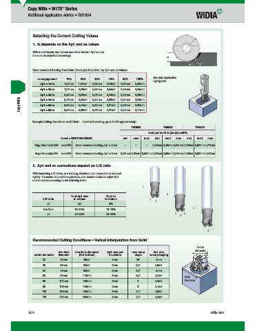
                    Selecting the Correct Cutting Values
                    1.  fz depends on the Ap1 and ae values

                    With round inserts, two factors can affect the hm: Ap1 and ae.
                  fz has to be adjusted accordingly.


                    Recommended Starting Feed Rate Values (fz) Related to the Ap1 and ae Values:
                                                                                 Example application
                    ae engagement  10%    20%    30%     40%    50%    100%
                                                                               highlighted.
                      Ap1 = 1mm   1,52mm  1,07mm  0,88mm  0,76mm  0,68mm  0,48mm
                      Ap1 = 2mm   1,07mm  0,76mm  0,62mm  0,54mm  0,48mm  0,34mm
                      Ap1 = 3mm   0,88mm  0,62mm  0,51mm  0,44mm  0,39mm  0,28mm
            Copy Mills   Ap1 = 4mm  0,76mm  0,54mm  0,44mm  0,38mm  0,34mm  0,24mm
                                                                      0,20mm
                                         0,44mm
                                                0,36mm
                                  0,62mm
                                                               0,26mm
                      Ap1 = 5mm
                                                        0,31mm
                      Ap1 = 6mm
                                                0,31mm
                                                        0,27mm
                                                               0,24mm
                                  0,54mm
                                         0,38mm
                                                                      0,17mm
                    Example Cutting Conditions for iC16mm... Insert in Pocketing, up to 3 L/D approximately:
                                                                    TN2505          TN6525           TN6540
                                                                             feed per tooth fz (mm)/ae>50%
                                insert = RDPX1604M0SN           min  med   max  min  med   max  min   med  max
                   Edge Geometry MM  ae>50%  Recommended starting Ap1 = 3mm  –  –  –  0,28mm 0,45mm 0,65mm 0,28mm 0,50mm 0,70mm
                   Edge Geometry MH  ae>50%  Recommended starting Ap1 = 3mm  0,28mm 0,35mm 0,50mm 0,28mm 0,50mm 0,75mm 0,28mm 0,60mm 0,80mm
                    2.  Ap1 and vc corrections depend on L/D ratio
                    With increasing L/D ratios, or overhang, vibrations can occur due to reduced
                  rigidity. To ensure successful application, it is recommended to adjust Ap1
                  and vc values according to the following table:
                                                                          L
                                                                                      L
                                     % of Ap1 max      % of vc
                       L/D ratio       to reduce       to reduce
                                                                                D
                         <2              0%              0%
                                                                                                    L
                       2<L/D<4         65–75%          10–15%
                         >4            80–95%          20–40%                                D


                                                                                                           D

                    Recommended Cutting Conditions • Helical Interpolation from Solid
                                                                                                       Cutter
                                                                                                     Diameter
                               min hole  max hole diameter  Ap1 max per   max ramp   Ap1 max
                   cutter diameter  diameter  (fl at bottom)  revolution  angle  when plunging
                       32       36mm        48mm          3mm          20°       3mm
                       50       69mm        84mm          8mm          9,5°     4,8mm
                       52       73mm        88mm          8mm          8,2°      5mm
                       63       95mm       110mm          8mm          5,5°     4,7mm            Hole
                       66       101mm      120mm          8mm          4°       4,2mm          Diameter
                       80       129mm      144mm          8mm          3°       4,1mm
                       100      169mm      184mm          8mm          2,4°     4,6mm
                       125      219mm      234mm          8mm          2,2°     4,4mm


                 K72                                                                                        widia.com


                     WID M
                  i
               V
                                    bl MIlli
                             16 I d
                                               Mill K072 K073 Mi h REBRANDN
                                           C
         L WID_Master16_IndexableMIlling_CopyMills_K072_K073_Minch_REBRAND.indd   72  b 10 20158 02AM              11/10/15   10:46 AM
   975   976   977   978   979   980   981   982   983   984   985