
Page 29 - Avtron Encoders Catalog
P. 29
Output Specifications
OUTPUT DESCRIPTION
OUTPUT Voltage
CHART 0 Input (Vin) Protection Maximum Cable Drive (feet) Most Avtron incremental encoders have
500 ft. [150m]@5V a two square wave output: A Quad B (A,
AV20, 1 5-28 VDC 250 ft. [75m]@12V B) 90° out of phase, with complements
AV25, 125 ft. [50m]@24V
HS25A, Reverse Voltage, Transient, (A–, B–). Marker pulses (Z) are available
HS35A 2 5-28 VDC Short Circuit 500 ft./150m on most units. Resolver and sine-cosine
Line 3* 5-15 VDC 1000 ft./300m outputs also available on Admotec
Driver components.
Options 5-28 VDC
4 500 ft./150m
(5V out)
* Available only on AV25, no short circuit protection for this option.
OUTPUT WAVEFORMS
OUTPUT Voltage A Quad B: Two Square Waves
CHART 1 Input (Vin) Protection Maximum Cable Drive (feet) 90° out of Phase
1000 ft [300m]@5V
Reverse Voltage, Transient, with Complements
1 5-24 VDC 500 ft [150m]@12V
Short Circuit
200 ft [60m]@24V
2 5-18 VDC Reverse Voltage, Transient 2000 ft. [600m] ØA
M3, M4,
M6, M7 Reverse Voltage, Transient,
Line 3 12-24 VDC Short Circuit (low)
Driver 1000 ft. [300m] ØB
Options 4 5-24 VDC Reverse Voltage, Transient,
(5V out)* Short Circuit
Reverse Voltage, Enhanced ØZ
6.5-24
8 Transient, Enhanced Short 1000 ft. [300m]
VDC**
Circuit –
* N/A on M6 and M7. ØA
** N/A on M3
–
OUTPUT Voltage Maximum Cable ØB
CHART 2 Input (+V) Protection Drive (feet)
1000 ft [300m]@5V –
AV45, AV56,
AV56S, AV67, 6 5-24 VDC 500 ft [150m]@12V ØZ
AV85, AV115 Reverse Voltage, 250 ft [75m]@24V
AV125, AV485, 5-24 V Enhanced Transient, –Direction Sensing
AV685, AV850, 8 (5-15 V*) Enhanced Short Circuit 2000 ft. [600m] –Zero Speed
HS35M, HS45, –Marker Pulse
XT45 Line 9 5-24 VDC 1000 ft. [300m]
Driver Options (5V out)
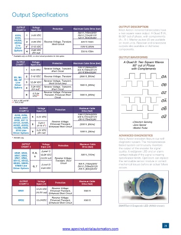
ADVANCED DIAGNOSTICS
* HS35M only. Many Avtron encoders feature our self-
diagnostic system. The microprocessor-
OUTPUT Voltage Maximum Cable based system continuously monitors
CHART 3 Input (+V) Protection Drive (feet)
the output of the encoder for signal
(Level 1) quality. A red/green LED and an alarm
XR4F, XR45, F, H, contact indicate if the signal is nearing
XR47, XR56, 5 12-24 VDC 500 ft. [150m]
XR67, XR85, (10.6V out) Reverse Voltage, specification limits. Operators can replace
XR115, XR125, Transient, Short the removable sensor module or correct
XR485, XR685, (Level 2) Circuit 500 ft. [150m]@5V mechanical issues before an actual failure
XR850 Line G, 7 500 ft. [150m]@12V
Driver Options 5-24 VDC 200 ft. [60m]@24V occurs.
OUTPUT Voltage Maximum Cable
CHART 4 Input (+V) Protection Drive (feet)
Reverse Voltage,
12-24 VDC
XRB1 Enhanced Transient, 1000 ft.
(10.6V out)
Enhanced Short Circuit
Reverse Voltage,
XRB2 12-24VDC Enhanced Transient, 1000 ft.
Enhanced Short Circuit
SMARTach II Diagnostic LED (AV850 shown)
29
www.apexindustrialautomation.com
www.apexindustrialautomation.com