Page 13 - EASA_AR100-2015_0815 APEX_IESCO
P. 13

EASA AR100-2015 Recommended Practice - Rev. August 2015                            Section 2, Page 7


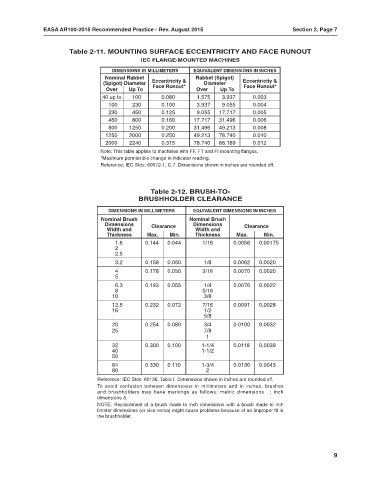
                        Table 2-11. MOUNTING SURFACE ECCENTRICITY AND FACE RUNOUT
                                                IEC FLANGE-MOUNTED MACHINES
                                      DIMENSIONS IN MILLIMETERS  EQUIVALENT DIMENSIONS IN INCHES
                                    Nominal Rabbet                Rabbet (Spigot)
                                   (Spigot) Diameter  Eccentricity &  Diameter   Eccentricity &
                                                                                  Face Runout*
                                                    Face Runout*
                                    Over    Up To                 Over    Up To
                                   40 up to  100      0.080       1.575   3.937      0.003
                                     100     230      0.100       3.937   9.055      0.004
                                     230     450      0.125       9.055  17.717      0.005
                                     450     800      0.160      17.717  31.496      0.006
                                     800    1250      0.200      31.496  49.213      0.008
                                    1250    2000      0.250      49.213  78.740      0.010
                                    2000    2240      0.315      78.740  88.189      0.012
                                  Note: This table applies to machines with FF, FT and FI mounting flanges.
                                  *Maximum permissible change in indicator reading.
                                  Reference: IEC Stds. 60072-1, C.7. Dimensions shown in inches are rounded off.


                                                   Table 2-12. BRUSH-TO-
                                               BRUSHHOLDER CLEARANCE
                                     DIMENSIONS IN MILLIMETERS   EQUIVALENT DIMENSIONS IN INCHES
                                  Nominal Brush                 Nominal Brush
                                    Dimensions     Clearance     Dimensions       Clearance
                                    Width and                     Width and
                                    Thickness     Max.   Min.     Thickness    Max.     Min.
                                       1.6       0.144  0.044       1/16      0.0056   0.00175
                                       2
                                       2.5
                                       3.2       0.158  0.050       1/8       0.0062   0.0020
                                       4         0.178  0.050       3/16      0.0070   0.0020
                                       5
                                       6.3       0.193  0.055       1/4       0.0076   0.0022
                                       8                            5/16
                                      10                            3/8
                                      12.5       0.232  0.072       7/16      0.0091   0.0028
                                      16                            1/2
                                                                    5/8
                                      20         0.254  0.080       3/4       0.0100   0.0032
                                      25                            7/8
                                                                     1
                                      32         0.300  0.100       1-1/4     0.0118   0.0039
                                      40                            1-1/2
                                      50
                                      64         0.330  0.110       1-3/4     0.0130   0.0043
                                      80                             2
                                 Reference: IEC Stds. 60136, Table I. Dimensions shown in inches are rounded off.
                                 To  avoid  confusion  between  dimensions  in  millimeters  and  in  inches,  brushes
                                 and  brushholders  may  have  markings  as  follows:  metric  dimensions  ❒;  inch
                                 dimensions ∆.
                                 NOTE: Replacement of a brush made to inch dimensions with a brush made to mil-
                                 limeter dimensions (or vice versa) might cause problems because of an improper fit in
                                 the brushholder.


                                                                                                               9
   8   9   10   11   12   13   14   15   16   17   18