
Page 9 - EASA_AR100-2015_0815 APEX_IESCO
P. 9
EASA AR100-2015 Recommended Practice - Rev. August 2015 Section 2, Page 3
2.13 ACCESSORIES 2.13.3 Terminal Boards
Terminal boards should be replaced if damaged,
2.13.1 Capacitors with components of the same ampacity and tempera-
Capacitors should be tested for rated capacitance ture rating of the original components.
and subjected to a high-potential test (see Paragraph
4.4). Capacitors should be replaced if damaged. 2.13.4 Space Heaters
Space heaters should be tested at operating volt-
2.13.2 Starting Components and Switches
Short circuit devices, centrifugal mechanisms, age for rated current or power and subjected to a
switches, and starting relays should be verified high-potential test (see Paragraph 4.4). They should
for electrical and mechanical operation at correct be replaced if damaged.
speed and voltage. These items should be replaced 2.13.5 Temperature Sensors
if damaged. Bearing and winding sensors or protectors should
be identical with or equivalent to the original devices
in electrical and thermal characteristics.
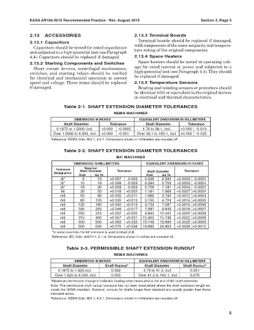
Table 2-1. SHAFT EXTENSION DIAMETER TOLERANCES
NEMA MACHINES
DIMENSIONS IN INCHES EQUIVALENT DIMENSIONS IN MILLIMETERS
Shaft Diameter Tolerance Shaft Diameter Tolerance
0.1875 to 1.5000, incl. +0.000 -0.0005 4.76 to 38.1, incl. +0.000 -0.013
Over 1.5000 to 6.500, incl. +0.000 -0.001 Over 38.1 to 165.1, incl. +0.000 -0.025
Reference: NEMA Stds. MG 1, 4.9.1. Dimensions shown in millimeters are rounded off.
Table 2-2. SHAFT EXTENSION DIAMETER TOLERANCES
IEC MACHINES
DIMENSIONS IN MILLIMETERS EQUIVALENT DIMENSIONS IN INCHES
Nominal
Tolerance Shaft Diameter Tolerance Tolerance
Designation Shaft Diameter
Over Up To Over Up To
j6* 6 10 +0.007 -0.002 0.236 0.394 +0.0003 -0.0001
j6* 10 18 +0.008 -0.003 0.394 0.709 +0.0003 -0.0001
j6* 18 30 +0.009 -0.004 0.709 1.181 +0.0004 -0.0002
k6 30 50 +0.018 +0.002 1.181 1.969 +0.0007 +0.0001
m6 50 80 +0.030 +0.011 1.969 3.150 +0.0012 +0.0004
m6 80 120 +0.035 +0.013 3.150 4.724 +0.0014 +0.0005
m6 120 180 +0.040 +0.015 4.724 7.087 +0.0016 +0.0006
m6 180 250 +0.046 +0.017 7.087 9.843 +0.0018 +0.0007
m6 250 315 +0.052 +0.020 9.843 12.402 +0.0020 +0.0008
m6 315 400 +0.057 +0.021 12.402 15.748 +0.0022 +0.0008
m6 400 500 +0.063 +0.023 15.748 19.685 +0.0025 +0.0009
m6 500 630 +0.070 +0.026 19.685 24.803 +0.0028 +0.0010
*In some countries the k6 tolerance is used instead of j6.
Reference: IEC Stds. 60072-1, C.1.4. Dimensions shown in inches are rounded off.
Table 2-3. PERMISSIBLE SHAFT EXTENSION RUNOUT
NEMA MACHINES
DIMENSIONS IN INCHES EQUIVALENT DIMENSIONS IN MILLIMETERS
Shaft Diameter Shaft Runout* Shaft Diameter Shaft Runout*
0.1875 to 1.625 incl. 0.002 4.76 to 41.3, incl. 0.051
Over 1.625 to 6.500, incl. 0.003 Over 41.3 to 165.1, incl 0.076
*Maximum permissible change in indicator reading when measured at the end of the shaft extension.
Note: The permissible shaft runout tolerance has not been established where the shaft extension length ex-
ceeds the NEMA standard. However, runouts for shafts longer than standard are usually greater than those
indicated above.
Reference: NEMA Stds. MG 1, 4.9.7. Dimensions shown in millimeters are rounded off.
5