
Page 55 - type de document
P. 55
EOS 90398-A_PHY-0004-Frames and transformer assembly
9. Generators installation/positioning
a. Notice that the generators are identified by a color code. There is usually a colored band
around the main power cable coming out of the back of each of the generators. The same
color code is used for all interface cables related to each plane. Color code and cable length
help identifying similar cables. However, always double-check for error.
b. The BLUE color code identifies the Lateral plane, and everything related to it. When
identifying the generator, look for a blue band around the power cable attached to the back of
the generator.
c. Similarly, the RED color identifies the Frontal plane, and everything related to it. A red band
on the generator power cable identifies the Frontal generator.
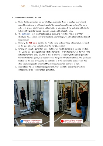
d. When positioning the generators notice that they will need to be facing in opposite direction.
The Lateral generator is positioned with the front of the HT tank facing in while the front of the
Lateral generator is facing out. This is done to improve accessibility to the Lateral generator
from the front of the gantry in a situation where the space in the back is limited. The spacing at
the back on this side of the gantry can be limited to fit the equipment in a small room. The
other side is not possible since the PDU door requires certain clearance to work.
e. Also notice if the site had seismic requirements, there should be a set of holes/anchors
indication the exact position of both generators.