
Page 128 - NEW Armstrong Book - 2
P. 128
high currents, the total drop can be high. If the gate is driven negative to turn off, which is common, this voltage (Vgs) adds to the source-drain drop, resulting in a Vsd of several volts, which can be significantly worse than other technolo- gies. The SiC FET, when conducting source to drain, has an I × R drop from the channel resistance similar to the GaN device, but this is only increased by the voltage across the body diode of the low-voltage cascoded Si MOSFET, which is relatively low. The resulting forward-voltage drop is typically about 1.5 V, better than SiC MOSFET or GaN performance.
Proving the reliability of the SiC FET
Wide-bandgap switches are robust, not least because of their inherently high temperature and high breakdown volt- age capability, and a particular advantage of the SiC FET is the absence of a SiC gate oxide, as is present in SiC MOSFETs, with their problems of degradation from high electric fields. The Si MOSFET in the cascode is a robust, low-voltage type with a high threshold voltage and thick gate oxide layer, addi- tionally protected by built-in Zener clamps. In practice, SiC FETs have shown themselves to be extremely reliable, with parts now routinely achieving automotive AEC-Q ratings.
Another important consideration is reliability during unin- tended stress events such as overvoltage and short-circuit. SiC FETs have a robust avalanche capability that is activated by the JFET drain gate breaking over. The resulting current through RG in Figure 3 drops voltage, turning on the JFET and clamping the overvoltage. The Si MOSFET now avalanches but in a highly controlled way, as avalanche-protection diodes are included in the fabrication of each cell and little power is dissipated. SiC MOSFETs also have an avalanche rating, but GaN HEMT cells do not, forcing manufacturers to rate the
FIGURE 6: SiC FETS WITHSTAND AN 8-μS SHORT-CIRCUIT STRESS FROM A 400-V BUS.
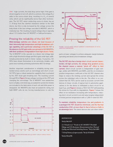
FIGURE 7: SiC FET SHORT-CIRCUIT CURRENT IS INDEPENDENT OF INITIAL JUNCTION TEMPERATURE.
parts at lower voltages to achieve adequate margin between operating and destructive breakdown voltage.
The SiC FET also has a benign short-circuit current charac- teristic: At high currents, the voltage drop gradient across the channel causes a natural “pinch off” effect to limit current. Short-circuit current is independent of gate volt- age, unlike with MOSFETs and IGBTs, and the on-resistance positive temperature coefficient of the SiC FET channel also helps to reduce the limiting current and spread the stress across the individual cells in the die. The effect is so con- sistent that SiC FETs can be used as accurate current-limit devices in linear circuits. A typical test in automotive appli- cations is for the device to withstand a short-circuit for at least 5 μs, and Figure 6 shows a 750-V SiC FET withstanding the stress for 8 μs with no degradation. Figure 7 shows the effect of on-resistance increasing with temperature, reduc- ing short-circuit current to an end value largely independent of initial junction temperature with a 1,200-V–rated SiC FET.
To maintain reliability, temperature rise and gradients in a packaged SiC FET should be minimized, and the thermal conductivity of SiC, at more than 3× that of silicon or GaN, is an advantage here. The latest devices also use silver sinter-
114
ASPENCORE GUIDE TO SILICON CARBIDE
REFERENCES 1bit.ly/38s315P
2J. P. Kozak et al. “Trends in SiC MOSFET Threshold Voltage and ON-Resistance Measurements from Thermal Cycling and Electrical Switching Stresses.” bit.ly/3jvL2BN
3“A brief history of supercascodes.” bit.ly/2Y24Swb 4bit.ly/2YewjTK
