
Page 132 - NEW Armstrong Book - 2
P. 132
118
ASPENCORE GUIDE TO SILICON CARBIDE
FIGURE 1: TYPICAL MODERN DATA CENTER POWER ARRANGEMENT
backup at this point, then convert directly down from 48 V to sub-1 V at the loads (Figure 1). This can obviate the need for a second intermediate bus, but the final, large down- conversion ratio poses its own efficiency problems, demand- ing high-performance semiconductor switches.
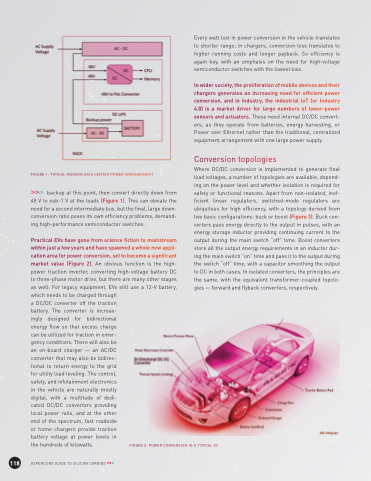
Practical EVs have gone from science fiction to mainstream within just a few years and have spawned a whole new appli- cation area for power conversion, set to become a significant market value (Figure 2). An obvious function is the high- power traction inverter, converting high-voltage battery DC to three-phase motor drive, but there are many other stages as well: For legacy equipment, EVs still use a 12-V battery, which needs to be charged through
Every watt lost in power conversion in the vehicle translates to shorter range; in chargers, conversion loss translates to higher running costs and longer payback. So efficiency is again key, with an emphasis on the need for high-voltage semiconductor switches with the lowest loss.
In wider society, the proliferation of mobile devices and their chargers generates an increasing need for efficient power conversion, and in industry, the industrial IoT (or Industry 4.0) is a market driver for large numbers of lower-power sensors and actuators. These need internal DC/DC convert- ers, as they operate from batteries, energy harvesting, or Power over Ethernet rather than the traditional, centralized equipment arrangement with one large power supply.
Conversion topologies
Where DC/DC conversion is implemented to generate final load voltages, a number of topologies are available, depend- ing on the power level and whether isolation is required for safety or functional reasons. Apart from non-isolated, inef- ficient linear regulators, switched-mode regulators are ubiquitous for high efficiency, with a topology derived from two basic configurations: buck or boost (Figure 3). Buck con- verters pass energy directly to the output in pulses, with an energy storage inductor providing continuing current to the output during the main switch “off” time. Boost converters store all the output energy requirements in an inductor dur- ing the main switch “on” time and pass it to the output during the switch “off” time, with a capacitor smoothing the output to DC in both cases. In isolated converters, the principles are the same, with the equivalent transformer-coupled topolo- gies — forward and flyback converters, respectively.
a DC/DC converter off the traction battery. The converter is increas- ingly designed for bidirectional energy flow so that excess charge can be utilized for traction in emer- gency conditions. There will also be an on-board charger — an AC/DC converter that may also be bidirec- tional to return energy to the grid for utility load leveling. The control, safety, and infotainment electronics in the vehicle are naturally mostly digital, with a multitude of dedi- cated DC/DC converters providing local power rails, and at the other end of the spectrum, fast roadside or home chargers provide traction battery voltage at power levels in the hundreds of kilowatts.
FIGURE 2: POWER CONVERSION IN A TYPICAL EV
