
Page 133 - NEW Armstrong Book - 2
P. 133
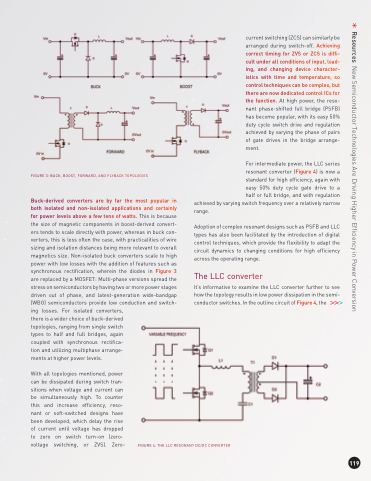
                                   FIGURE 3: BUCK, BOOST, FORWARD, AND FLYBACK TOPOLOGIES
Buck-derived converters are by far the most popular in both isolated and non-isolated applications and certainly for power levels above a few tens of watts. This is because the size of magnetic components in boost-derived convert- ers tends to scale directly with power, whereas in buck con- verters, this is less often the case, with practicalities of wire sizing and isolation distances being more relevant to overall magnetics size. Non-isolated buck converters scale to high power with low losses with the addition of features such as synchronous rectification, wherein the diodes in Figure 3 are replaced by a MOSFET: Multi-phase versions spread the stress on semiconductors by having two or more power stages driven out of phase, and latest-generation wide-bandgap (WBG) semiconductors provide low conduction and switch- ing losses. For isolated converters,
current switching (ZCS) can similarly be arranged during switch-off. Achieving correct timing for ZVS or ZCS is diffi- cult under all conditions of input, load- ing, and changing device character- istics with time and temperature, so control techniques can be complex, but there are now dedicated control ICs for the function. At high power, the reso- nant phase-shifted full bridge (PSFB) has become popular, with its easy 50% duty cycle switch drive and regulation achieved by varying the phase of pairs of gate drives in the bridge arrange- ment.
For intermediate power, the LLC series resonant converter (Figure 4) is now a standard for high efficiency, again with easy 50% duty cycle gate drive to a half or full bridge, and with regulation
achieved by varying switch frequency over a relatively narrow range.
Adoption of complex resonant designs such as PSFB and LLC types has also been facilitated by the introduction of digital control techniques, which provide the flexibility to adapt the circuit dynamics to changing conditions for high efficiency across the operating range.
The LLC converter
It’s informative to examine the LLC converter further to see how the topology results in low power dissipation in the semi- conductor switches. In the outline circuit of Figure 4, the
   there is a wider choice of buck-derived topologies, ranging from single switch types to half and full bridges, again coupled with synchronous rectifica- tion and utilizing multiphase arrange- ments at higher power levels.
With all topologies mentioned, power can be dissipated during switch tran- sitions when voltage and current can be simultaneously high. To counter this and increase efficiency, reso- nant or soft-switched designs have been developed, which delay the rise of current until voltage has dropped to zero on switch turn-on (zero- voltage switching, or ZVS). Zero-
FIGURE4:THELLCRESONANTDC/DCCONVERTER
  119
Resources New Semiconductor Technologies Are Driving Higher Efficiency in Power Conversion
