
Page 34 - NEW Armstrong Book - 2
P. 34
The Fabrication Processes
and Substrate Features
of Silicon Carbide
S
ilicon carbide boules and substrates contain a vari- ety of crystal imperfections, both extended and point-like. The density of point defects in SiC boules
By Gianfranco Di Marco
tion line. It may be described as an edge of an extra plane of atoms within a crystal structure in which regions of com- pression and tension are associated with an edge dislocation. Figure 1 clarifies the nature of dislocations.
A micropipe, also called a microtube or pinhole defect, is a crystallographic defect, similar to a hollow core, associ- ated with a super-screw dislocation that possesses a large Burgers vector — several times the unit cell dimension. The high stress along the center core of this super-screw disloca- tion (see Figure 1) causes preferential sublimation during the growth process and, therefore, the hollow core nature of the defect. These hollow-core screw dislocations typically run parallel to the growth direction through the entire SiC boule. In other words, a screw dislocation transforms successive
is quite high, in the 1014- to 1016-cm–3 range.
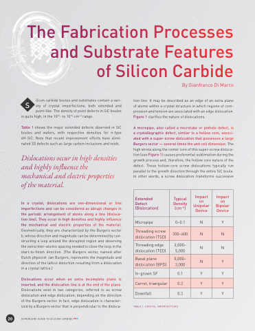
Table 1 shows the major extended defects observed in SiC boules and wafers, with respective densities for n-type 4H-SiC. Note that recent improvement efforts have elimi- nated 3D defects such as large carbon inclusions and voids.
Dislocations occur in high densities and highly influence the mechanical and electric properties of the material.
In a crystal, dislocations are one-dimensional or line imperfections and can be considered as abrupt changes in the periodic arrangement of atoms along a line (disloca- tion line). They occur in high densities and highly influence the mechanical and electric properties of the material. Geometrically, they are characterized by the Burgers vector b, whose direction and magnitude can be determined by con- structing a loop around the disrupted region and observing the extra inter-atomic spacing needed to close the loop in the start-to-finish direction. (The Burgers vector, named after Dutch physicist Jan Burgers, represents the magnitude and direction of the lattice distortion resulting from a dislocation in a crystal lattice.)
Dislocations occur when an extra incomplete plane is inserted, and the dislocation line is at the end of the plane. Dislocations exist in two categories, referred to as screw dislocation and edge dislocation, depending on the direction of the Burgers vector. In fact, edge dislocation is character- ized by a Burgers vector that is perpendicular to the disloca-
TABLE 1: CRYSTAL IMPERFECTIONS
Extended Defect (Dislocation)
Typical Density (cm–2)
Impact on Unipolar Device
Impact on Bipolar Device
Micropipe
0–0.1
N
Y
Threading screw dislocation (TSD)
300–600
N
N
Threading edge dislocation (TED)
2,000– 5,000
N
N
Basal plane dislocation (BPD)
5,000– 3,000
N
Y
In-grown SF
0.1
Y
Y
Carrot, triangular
0.3
Y
Y
Downfall
0.3
Y
Y
20
ASPENCORE GUIDE TO SILICON CARBIDE
