
Page 55 - NEW Armstrong Book - 2
P. 55
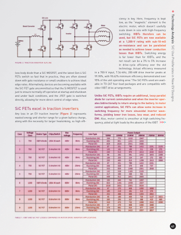
                                   FIGURE 2: TRACTION INVERTER OUTLINE
loss body diode than a SiC MOSFET, and the latest Gen 4 SiC FETs switch so fast that in practice, they are often slowed down with gate resistance or small snubbers to achieve ideal edge rates. Alternatively, devices are becoming available with the SiC FET gate uncommitted so that the Si MOSFET is used just to ensure normally off operation at startup and shutdown and under fault conditions, and the JFET gate is switched directly, allowing for more direct control of edge rates.
SiC FETs excel in traction inverters
Any loss in an EV traction inverter (Figure 2) represents wasted energy and shorter range for a given battery charge, along with the necessity for larger heatsinking, so high effi-
ciency is key. Here, frequency is kept low, as the “magnetic” element is the electric motor, which doesn’t usefully scale down in size with high-frequency switching. IGBTs therefore can be used, but SiC FETs are now available at a 1,200-V rating with sub-10-mΩ on-resistance and can be paralleled as needed to achieve lower conduction losses than IGBTs. Switching energy is far lower than for IGBTs, and the net result can be a 3% to 5% increase in drive-cycle efficiency over the old technology. Actual efficiency measured
in a 700-V input, 7.34-kHz, 200-kW drive inverter peaks at 99.98%, with 98.62% minimum efficiency demonstrated over 95% of the unit operating area.2 The SiC FETs used are avail- able in TO-247 four-lead packages and are compatible with older IGBT drive arrangements.
Unlike SiC FETs, IGBTs require an additional, lossy parallel diode for current commutation and when the inverter oper- ates bidirectionally to return energy to the battery. In motor control applications, SiC FETs can allow some increase in switching frequency for more sinusoidal inverter wave- forms, yielding lower iron losses, less wear, and reduced EMI. Also, motor control is smoother at high switching fre- quency, aided at light loads by the absence of the IGBT
    TABLE 1: IGBT AND SiC FET LOSSES COMPARED IN MOTOR DRIVE INVERTER APPLICATIONS
 41
Technology Analysis SiC Use Proliferates in New EV Designs
