
Page 56 - NEW Armstrong Book - 2
P. 56
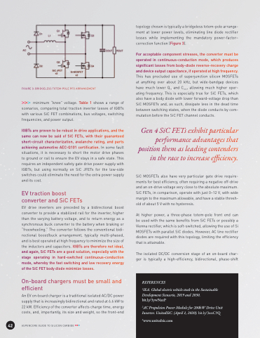
                                 FIGURE 3: BRIDGELESS TOTEM-POLE PFC ARRANGEMENT
minimum “knee” voltage. Table 1 shows a range of scenarios, comparing total traction inverter losses of IGBTs with various SiC FET combinations, bus voltages, switching frequencies, and power output.
IGBTs are proven to be robust in drive applications, and the same can now be said of SiC FETs, with their guaranteed short-circuit characterization, avalanche rating, and parts achieving automotive AEC-Q101 certification. In some fault situations, it is necessary to short the motor drive phases to ground or rail to ensure the EV stays in a safe state. This requires an independent safety gate drive power supply with IGBTs, but using normally on SiC JFETs for the low-side switches could eliminate the need for the extra power supply and its cost.
EV traction boost
converter and SiC FETs
EV drive inverters are preceded by a bidirectional boost converter to provide a stabilized rail for the inverter, higher than the varying battery voltage, and to return energy as a synchronous buck converter to the battery when braking or “freewheeling.” The converter follows the conventional bidi- rectional boost/buck arrangement, typically multi-phased, and is best operated at high frequency to minimize the size of the inductors and capacitors. IGBTs are therefore not ideal, and again, SiC FETs are a good solution, especially with the stage operating in hard-switched continuous-conduction mode, whereby the fast switching and low recovery energy of the SiC FET body diode minimize losses.
On-board chargers must be small and
efficient
An EV on-board charger is a traditional isolated AC/DC power supply that is increasingly bidirectional and rated at 6.6 kW to 22 kW. Efficiency of the converter affects charge time, energy costs, and, importantly, its size and weight, so the front-end
topology chosen is typically a bridgeless totem-pole arrange- ment at lower power levels, eliminating line diode rectifier losses while implementing the mandatory power-factor– correction function (Figure 3).
For acceptable component stresses, the converter must be operated in continuous-conduction mode, which produces significant losses from body-diode reverse-recovery charge and device output capacitance, if operated at high frequency. This has precluded use of superjunction silicon MOSFETs at anything over about 20 kHz, but wide-bandgap devices have much lower Qrr and Coss, allowing much higher oper- ating frequency. This is especially true for SiC FETs, which also have a body diode with lower forward-voltage drop than SiC MOSFETs and, as such, dissipate less in the dead time between switching states, when the diode conducts by com- mutation before the SiC FET channel conducts.
Gen 4 SiC FETs exhibit particular performance advantages that position them as leading contenders in the race to increase efficiency.
SiC MOSFETs also have very particular gate drive require- ments for best efficiency, often requiring a negative off-drive and an on-drive voltage very close to the absolute maximum. SiC FETs, in comparison, operate with just 0–12 V, with wide margin to the maximum allowable, and have a stable thresh- old of about 5 V with no hysteresis.
At higher power, a three-phase totem-pole front end can be used with the same benefits from SiC FETs or possibly a Vienna rectifier, which is soft-switched, allowing the use of Si MOSFETs with parallel SiC diodes. However, AC line rectifier diodes are required with this topology, limiting the efficiency that is attainable.
The isolated DC/DC conversion stage of an on-board char- ger is typically a high-efficiency, bidirectional, phase-shift
    42
ASPENCORE GUIDE TO SILICON CARBIDE
    REFERENCES
1IEA. Global electric vehicle stock in the Sustainable Development Scenario, 2019 and 2030. bit.ly/3ywNaxP
2AC Propulsion Power Module for 200kW Drive Unit Inverter. UnitedSiC. (April 1, 2020). bit.ly/3xssC9Q
3www.unitedsic.com
