
Page 157 - Driving Commercial Vehicles Manual+
P. 157
driving commercial vehicles
If a constant supply of compressed air were directed through a pipe that’s
one-inch square (see diagram on the previous page), and if a one-inch square
plug were placed in the pipe, the compressed air would push against the
plug. Holding a scale against the plug would register how many pounds of
force the air was exerting against the plug.
If the scale registered 10 pounds, for example, then it could be said that the
force was 10 pounds on the one square inch surface of the plug. This would
be 10 p.s.i. or 68.9 kPa.
The more the air’s compressed (that is, the greater the air pressure), the
greater the force that would be exerted on the face of the plug.
Basic air brake components
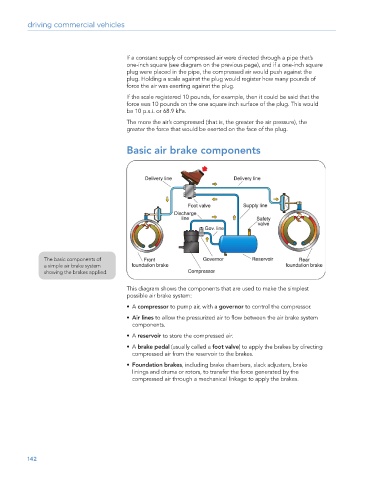
The basic components of
a simple air brake system
showing the brakes applied.
This diagram shows the components that are used to make the simplest
possible air brake system:
• A compressor to pump air, with a governor to control the compressor.
• Air lines to allow the pressurized air to flow between the air brake system
components.
• A reservoir to store the compressed air.
• A brake pedal (usually called a foot valve) to apply the brakes by directing
compressed air from the reservoir to the brakes.
• Foundation brakes, including brake chambers, slack adjusters, brake
linings and drums or rotors, to transfer the force generated by the
compressed air through a mechanical linkage to apply the brakes.
142