
Page 124 - JOJAPS_VOL15
P. 124
JOJAPS – JOURNAL ONLINE JARINGAN PENGAJIAN SENI BINA
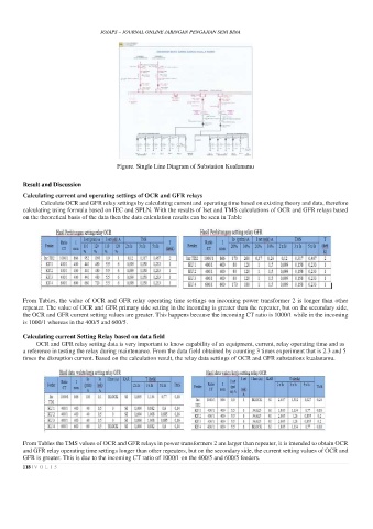
Figure. Single Line Diagram of Substation Kualanamu
Result and Discussion
Calculating current and operating settings of OCR and GFR relays
Calculate OCR and GFR relay settings by calculating current and operating time based on existing theory and data, therefore
calculating using formula based on IEC and SPLN. With the results of Iset and TMS calculations of OCR and GFR relays based
on the theoretical basis of the data then the data calculation results can be seen in Table
From Tables, the value of OCR and GFR relay operating time settings on incoming power transformer 2 is longer than other
repeater. The value of OCR and GFR primary side setting in the incoming is greater than the repeater, but on the secondary side,
the OCR and GFR current setting values are greater. This happens because the incoming CT ratio is 1000/1 while in the incoming
is 1000/1 whereas in the 400/5 and 600/5.
Calculating current Setting Relay based on data field
OCR and GFR relay setting data is very important to know capability of an equipment, current, relay operating time and as
a reference in testing the relay during maintenance. From the data field obtained by counting 3 times experiment that is 2.3 and 5
times the disruption current. Based on the calculation result, the relay data settings of OCR and GFR substations kualanamu.
From Tables the TMS values of OCR and GFR relays in power transformers 2 are larger than repeater, it is intended to obtain OCR
and GFR relay operating time settings longer than other repeaters, but on the secondary side, the current setting values of OCR and
GFR is greater. This is due to the incoming CT ratio of 1000/1 on the 400/5 and 600/5 feeders.
118 | V O L 1 5