
Page 18 - jojaps_vol14
P. 18
Tan Chin Chai / JOJAPS – JOURNAL ONLINE JARINGAN PENGAJIAN SENI BINA
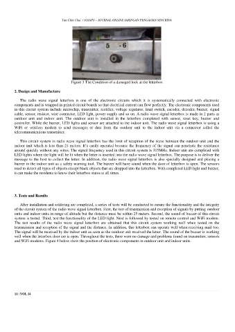
Figure 3 The Condition of a damaged lock at the letterbox
2. Design and Manufacture
The radio wave signal letterbox is one of the electronic circuits which it is systematically connected with electronic
components and is wrapped in printed circuit boards so that electrical current can flow perfectly. The electronic components used
in this circuit system include microchip, transmitter, rectifier, voltage regulator, limit switch, encoder, decoder, buzzer, signal
cable, sensor, resistor, wire connector, LED light, power supply and so on. A radio wave signal letterbox is made in 2 parts as
outdoor unit and indoor unit. The outdoor unit is installed in the letterbox completed with sensor, reset key, buzzer and
controller. While the buzzer, LED lights and sensor are attached to the indoor unit. The radio wave signal letterbox is using a
WiFi or wireless modem to send messages or data from the outdoor unit to the indoor unit via a connector called the
telecommunications transmitter.
This circuit system in radio wave signal letterbox has the limit of reception of the wave between the outdoor unit and the
indoor unit which is less than 25 meters. It’s easily operated because the frequency of the signal can penetrate the resistance
around quickly without any wires. The signal frequency used in this circuit system is 315MHz. Indoor unit are completed with
LED lights where the light will be lit when the letter is inserted into the radio wave signal letterbox. The purpose is to deliver the
message to the host to collect the letter. In addition, the radio wave signal letterbox is also specially designed and placing a
buzzer in the indoor unit as a safety warning tool. The buzzer will have sound when the door of letterbox is open. The sensors
used to detect all types of objects except black objects that are dropped into the letterbox. With completed LED light and buzzer,
it can make the residents to know their letterbox status at all times.
3. Tests and Results
After installation and soldering are completed, a series of tests will be conducted to ensure the functionality and the integrity
of the circuit system of the radio wave signal letterbox. First, the test of transmission and reception of signals by putting outdoor
units and indoor units in range of altitude but the distance must be within 25 meters. Second, the sound of buzzer of this circuit
system is tested. Third, test the functionality of the LED light. Next is followed by tested on remote control and WiFi modem.
The test results of the radio wave signal letterbox are obtained that this circuit system working well when tested on the
transmission and reception of the signal and the distance. In addition, this letterbox can operate well when receiving mail too.
The signal will be received by the indoor unit as soon as the outdoor unit received the letter. The sound of the buzzer is working
well when the letterbox door are is open. Throughout the tests, there were no damage and problems found on transmitter, sensors
and WiFi modems. Figure 4 below show the position of electronic components in outdoor unit and indoor units.
11 | VOL 14