


Page 51 - M. Abrahim Thesis
P. 51
Computer Network                                                             2021

            into two links) and the backbone tree (a backbone trunk has branch nodes with links hanging
            from it).  https://www.youtube.com/watch?v=ZmLxb8HzQX4&t=60s


                 2.10.1.5     Full-Mesh and Partial-Mesh Topologies

                   The full-mesh topology connects all devices (nodes) to each other for redundancy and
            fault  tolerance.  The  wiring  in  a  full-mesh  topology  has  very  distinct  advantages  and
            disadvantages. The advantage is that every node is connected physically to every other node,
            which creates a redundant connection. If any link fails, information can flow through many other
            links to reach its destination. The primary disadvantage is that for anything more than a small
            number of nodes, the amount of media for the links and the number of the connections on the
            lines becomes overwhelming. Implementing a full-mesh topology is expensive and difficult.

                    The full-mesh topology is usually implemented in WANs between routers.

                   In a partial-mesh topology, at least one device maintains multiple connections to others
            without being fully meshed, as shown in Figure below. A partial-mesh topology still provides
            redundancy by having several alternative routes. If one route cannot be used, the data takes
            another  route,  even  if  it  is  longer.  The  partial-mesh  topology  is  used  for  many
            telecommunications backbones, as well as the Internet.

                   https://www.youtube.com/watch?v=8UZlwhiWKmA


            2.10.2 Logical Topology

                   A network’s logical topology is how the hosts communicate across the medium.


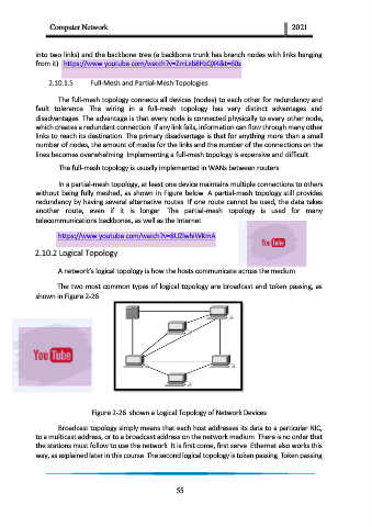
                   The two most common types of logical topology are broadcast and token passing, as
            shown in Figure 2-26.


                              Figure 2-26  shown a Logical Topology of Network Devices

                   Broadcast topology simply means that each host addresses its data to a particular NIC,
            to a multicast address, or to a broadcast address on the network medium. There is no order that
            the stations must follow to use the network. It is first come, first serve. Ethernet also works this
            way, as explained later in this course. The second logical topology is token passing. Token passing


                                                         55

