Page 5 - Zavation 2 Cervical Plate Systems Booklet - Hensler 2019
P. 5

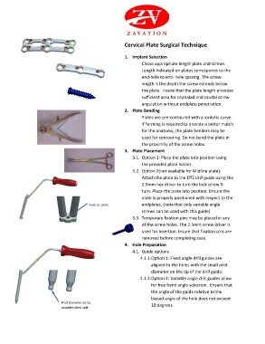
Cervical Plate Surgical Technique


                                                           1. Implant Selection
                                                                   Chose appropriate length plate and screws.
                                                                   Length indicated on plates corresponds to the
                                                                   end-hole to end- hole spacing. The screw
                                                                   length is the depth the screw extends below
                                                                   the plate.  Insure that the plate length provides
                                                                   sufficient area for cephalad and caudal screw
                                                                   angulation without endplate penetration.
                                                           2. Plate Bending
                                                                   Plates are pre-contoured with a lordotic curve.
                                                                   If forming is required to provide a better match
                                                                   for the anatomy, the plate benders may be
                                                                   used for contouring. Do not bend the plate in
                                                                   the proximity of the screw holes.
                                                           3. Plate Placement
                                                              3.1.  Option 1: Place the plate into position using
                                                                   the provided plate holder.
                                                              3.2.  Option 2(not available for Midline plate):
                                                                   Attach the plate to the DTS drill guide using the
                                                                   2.5mm hex driver to turn the lock screw ¼
                                                                   turn. Place the plate into position. Ensure the
                                                                   plate is properly positioned with respect to the
                                           Lock to  plate          endplates. (note that only variable angle
                                           uses                    screws can be used with this guide)
                                           screwdriver
                                                              3.3.  Temporary fixation pins may be placed in any
                                                                   of the screw holes. The 2.5mm screw driver is
                                                                   used for insertion. Insure that fixation pins are
                                                                   removed before completing case.
                                                           4. Hole Preparation
                                                              4.1.  Guide options
                                                                  4.1.1. Option 1: Fixed angle drill guides are
                                                                       aligned to the holes with the small pilot
                                                                       diameter on the tip of the drill guide.
                                                                  4.1.2. Option 2: Variable angle drill guides allow
                                                                       for free hand angle selection.  Ensure that
                                                                       the angle of the guide relative to the
                                                                       biased angle of the hole does not exceed
                              Pilot diameter on tip
                              provides fixed anle                      10 degrees.
   1   2   3   4   5   6   7   8   9   10