
Page 6 - Zavation 2 Cervical Plate Systems Booklet - Hensler 2019
P. 6
4.1.3. Option 3(not available for Midline plate):
For the caudal and cephalad holes, the
DTS guide provides a 10 degree screw
angulation. (note that only the variable
angle screws can be used with this guide)
4.2. The hole can be created with the awl (which
creates an 11mm deep hole), or drill. If using
the drill, select the drill that corresponds to the
screw length and attach to the jeweler handle
with the quick release. Both the drills and the
awl should be advanced until they stop on the
drill guide to achieve the depth specified.
5. Screw Insertion
5.1. Load the appropriate length screw on the
2.5mm screw driver. The screw driver has a
self-retaining insert to hold the screw during
insertion. Advance screw until it seats firmly
inside the pocket in the plate. Screws must be
seated completely to allow screw locks to be
engaged.
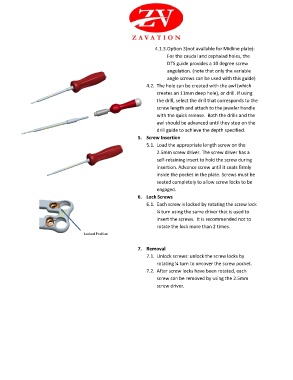
6. Lock Screws
6.1. Each screw is locked by rotating the screw lock
¼ turn using the same driver that is used to
insert the screws. It is recommended not to
rotate the lock more than 2 times.
Locked Position
7. Removal
7.1. Unlock screws: unlock the screw locks by
rotating ¼ turn to uncover the screw pocket.
7.2. After screw locks have been rotated, each
screw can be removed by using the 2.5mm
screw driver.